User Tools
Table of Contents
5. Structure Manager
5.1. basics
5.1.1. introduction
The Structure Manager allows you to create general product structures (BOM = Bill of Material) that can be configured to display the product structure at a specific time or for a specific unit, such as
- The valid component structure of an assembly
- A specific approved manufacturing design of the product
- The current design structure in product development
- The product structure that was valid on a certain date
- A specific variant of a product
By creating a single generic structure that can then be configured to meet individual user requirements, assembly structures do not need to be duplicated. This avoids the associated problems of maintenance, redundant information and search complexity. The list is similar to the bill of materials that design departments use to list manufacturing information.
5.1.2. opening the structure manager
Start the Structure Manager (PSE) in the navigation window of the TC Client.

This opens the application with a new and empty window.

To open an existing BOM view revision status (BVR = BOM View Revision) in the Structure Manager, use one of the following options:
- Double click on the parts list view (View)
 |  |
- Right mouse button on selected item / item revision or view → Send to → structure management
 | 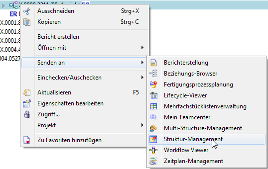 |
5.1.3 Overview of the UI

| 1. | Display of the assembly structure in the form of expandable tree diagrams in list form |
| 2. | Display of the columns can be configured as desired. |
| 3. | Usually corresponds to the design structure coming from the CAD → However, components without geometry (additive, auxiliary materials, …) can also be stored here |

| 1. | Modified? YES/NO |
| 2. | subassembly |
| 3. | Component |
5.1.4. Anpassen der Oberfläche
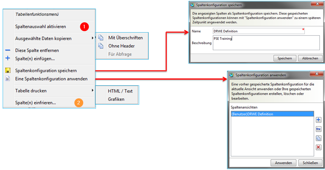
| 1. | Switch between column and row selection |
| 2. | Freeze desired columns while scrolling. Same column function as in MS Excel. |
5.2 Introduction to the Structure Manager
5.2.1. change status rule
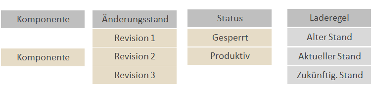
For each BOM entry in the structure, this configuration method determines the change status of the associated element, which is configured according to the change status attributes - for example, release status, validity, or owner. When you open a structure in the Structure Manager, a change status rule is always active. This rule consists of various parameters, which Teamcenter uses for evaluation. According to the criteria defined in the change status rule, an available change status is provided for each element in the structure. If no change statuses are found, the Structure Manager displays three question marks ??? for the corresponding entry and the structure cannot be extended beyond this point.

Assembly structures can be changed in the Structure Manager to
- specific times
- with certain characteristics
can be considered at any time.
Future developments can also be taken into account by indicating new revisions that are still in progress.

When you open a structure in the Structure Manager, always a change status rule is active. To apply a change status rule to the current product structure, use the icon in the toolbar or call the following menu function → Tools → Change status rule.
5.2.2. precise / imprecise assembly structures
The Structure Manager allows you to create and manage the following assembly accuracies:
Imprecise assemblies → are dynamic element structures
An imprecise assembly contains links (items) to parts of its component.
With imprecise assemblies you can see the product structure (BOM) that is configured with the relevant element change statuses. The change status rule selected for the window is taken into account.
Precise assemblies → are fixed structures of specific part change states
A precise assembly contains links (items) to elementary change states of its component. If you change a component to a new change status, you must update the assembly manually so that the old change status of the component is removed and the new change status is added.
(In the future, FFG will work with imprecise assembly structures)

| 1. | Precise = there are only Revisionen built in |
| 2. | New revisions have no effect on the defined assembly → must always be updated manually |
| 3. | Imprecise = Components are installed as Item |
| 4. | New revisions are automatically integrated. |
Precise assemblies are helpful in the case of prescribed, so-called revision control, such as in the case of safety-relevant or documentation-obligatory products. Changes to approved precision assemblies always result in a revision of the entire assembly.
5.3 Working with the Structure Manager
5.3.1. creating a structure
You can create the product structure manually in Teamcenter, import it from the CAD system or clone an existing structure to use it as a basis for a structure. Generally, assemblies are created in the MCAD system and transferred to Teamcenter.
Create an assembly in Teamcenter Structure Manager:
| a. | |
| b. | Send an existing item revision in the context menu with → Send to → Structure Management. Now the components can be added. |
In both cases, a BOM view is automatically assigned to the revision, following the change status rule.
The designer creates his assembly in the integrated CAD system and saves it in Teamcenter. This means that all modifications in the native CAD design are automatically saved and synchronized in Teamcenter.
5.3.2. create a structure object
Create a new BOM view change status directly on a previously selected item revision in the menu File → New → BOM view change status or CTRL+B.

| View Type | An attribute of a BOM view change state that indicates its purpose (such as design, manufacturing). The administrator can define any number of view types. |
| Change Status | Element ID and Change Status ID |
| precision option | Definition of a precise or imprecise structure |
5.3.3 Creating components
Once the assembly structure is created, the component can be added using various approaches.
| 1. | Create item with File → New → Item |
| 2. | Copy / Paste method: a.) Copy the component (or subassembly) to “My Teamcenter” (CTRL+C) b.) Switch to the Structure Manager c.) Select the line under which the component is to be inserted d.) Paste with (CTRL+V) |
| 3. | Quickly add components from the status bar Menu → Edit → Add |

| 1. | Open object by name |
| 2. | Search Item-ID |
| 3. | Open the corresponding item with a double click |
| 4. | Select desired change status |
| 5. | Define number of positions |
| 6. | Assign position number |
5.3.4 Changing and deleting components
 | Delete Component Removes the selected component and deletes the item from the database irretrievably! |
 | The selected component is removed This action only affects the removal of the component from the assembly structure. The data record of the component is retained. |
5.3.5 Replacing components
| 1. | Menu item → Edit → Replace (without…) |
| The selected component is immediately replaced with the one from the clipboard. | |
| 2. | Menu item → Edit → Replace |
| A selection dialog appears in which the element ID of the replacing component can be entered. If the replacing component is contained in the clipboard, the fields for the element ID and change status are already filled in. You can change the ID if necessary, but not the part name; the part name is derived from the part ID entered |

| 1. | Open object by name |
| 2. | Search Item-ID |
| 3. | Open the corresponding item with a double click |
| 4. | Select desired change status |
| 5. | Define replacing object |
| 6. | Confirm process |
5.3.6. item numbers and quantities
An adjustment of the position numbers (also Search Number / Find No.) causes an update of the display sequence of the BOM structure.

If no special unit of measurement is defined in the item, the system uses the unit of measure Every/Each. In the system, the default entry Each is configured to Piece. The specified value must be an integer.
A unit of measure at the item (not in the structure) cannot be changed afterwards, as long as this is built into a structure!
The Quantity column is the total quantity represented by the item, which is greater than one if the item is compressed or if the component serves as a collective item.
5.3.7. packed display of lines
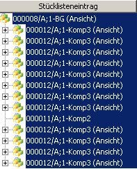 | Select the lines that you want to pack or unpack. The item number (search number) must be identical for all components. |
 | Perform packing / Unpack selected lines |
 | Result |
5.3.8. forced components
CAD components which are positioned in the CAD system with an assembly constraint are marked with a corresponding icon in the Structure Management and receive the attribute Position constrained = TRUE in the structure component properties.

5.3.9. arrangements
In CAD, you can define arrangements to determine alternative items for components in the assembly and save these alternatives with the assembly. For example, the assembly of a machine can have several arrangements if individual components are to represent different usage positions of the machine.
The position of certain components is overwritten accordingly. You can also suppress components in a particular arrangement, for example, to hide ejectors. If you manage an assembly with arrangements in Teamcenter, each component in CAD has a corresponding position in Teamcenter and each overwriting or suppression has a corresponding absolute position.
If the structure contains orders, permanent transformations are applied to all orders by default.
5.3.10. Structural component properties
You can add non-geometric components to assemblies in the MCAD system or in Structure Management. These do not have geometry for display in the graphics window of the CAD system. Examples of non-geometric components are
- Lacquer
- Adhesive
- Lubricants
- Hydraulic fluids
- Instruction leaflet
A component used only as reference is removed from the parts list of its parent component in the MCAD system and from the view of its parent component in Teamcenter Structure Manager. Examples for reference components are
- Auxiliary or dummy parts
- Supplied or purchased parts whose structure is used in CAD, but is purchased as a complete part. Therefore, only one item should appear in the BOM.
In the CAD system NX the properties of the corresponding components can be defined. A multiple selection is possible.
 | Right click on desired part → Properties |
 |
|
 | Component serves exclusively as reference |
 |
|
 | Component is not geometric |
 |
In Teamcenter Structure Manager the reference components are not displayed. Of course, this also applies to the components suppressed in the MCAD system.
The non-geometric components get the attribute UG-Geometry=NO and are marked with a special icon. Components with a UOM <> each (each)/piece are automatically loaded into the CAD as reference components.
If a sub-assembly is marked as non-geometric, all underlying components are not loaded into NX either.

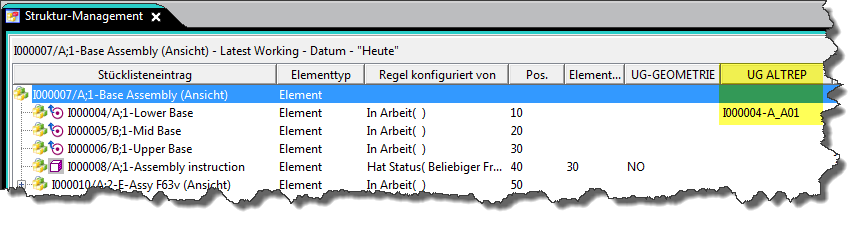
Altreps (alternative representations) can be used to define different physical configurations or shapes of a flexible part (for example, a tube or hose).
In Teamcenter Structure Manager, alternative representations of components are defined and displayed using the column UG ALTREP.
5.3.11. Capturing configurations
Teamcenter has, among others, the following formats for permanently recording the configuration of a structure.
5.3.11.1. Snapshot
A snapshot is a workspace folder that stores a reference to all element change states contained in a configured structure.
You can use a snapshot to save the product structure with a particular configuration and implemented change state rules and display it again at a later time by sending the snapshot folder to the Structure Manager. However, all change statuses that have not been released can be changed, such as linked data and CAD models.
For this reason, it makes sense to create snapshots only of completely released product structures!
5.3.11.2. Snapshot manuell erstellen
| 1. | Configure the structure to be saved by applying the corresponding change status rule. |
| 2. | Create via → File → New → Snapshot |
 |
|
| 3. | A new folder (type Snapshot) with the referenced snapshot data is stored in the folder “Newstuff”. |
| 4. | It is recommended to attach the snapshot to an element change status. a.) Copy the snapshot folder to the clipboard b.) Select the element modification state and choose → Edit → Insert content c.) Select the type 2D snapshot and confirm the dialog |
 | You open a snapshot by simply sending it to the Structure Manager. |
5.3.11.3. Baseline
Baselines correspond approximately to a development status documentation, which contains a copy of the entire “in progress” data for the structure.
With a baseline, Teamcenter creates a new dataset and attaches a copy of the configured structure to it. Teamcenter creates a new change status in the structure for each unreleased change status and releases it with a predefined status, for example with the status Baseline. A baseline change state rule is then applied to the base configuration (for example to change states with the status Production) and all new change states created by “Baseline” are also added. This procedure configures a fully released structure and thus ensures that the models are always the same at the time of baseline creation.
Create baselines sparingly, as each baseline creates a fully released structure and thus (possibly) many new element change states and copies of the linked data and CAD models are created!
5.4. comparison of product structures
5.4.1. basics
With the command “Compare” you can display and compare the structural differences. The comparison is performed on the extended structure and you can select the areas of the structure to be compared. You can define the change status rule and the variant rule separately for each structure, allowing different configurations to be compared.
The comparison determines the differences in number and change status in three modes:
| 1. | Single-level |
| Compares only the first level of product structures. | |
| 2. | Multilevel |
| Performs a one-step comparison at the top level and then performs further one-step comparisons on the subassemblies that occur in the two product structures. | |
| 3. | Low level only |
| Compares only the parts at the lowest level in the product structure, ignoring any assemblies that exist above it in the meantime. This is useful for checking whether individual parts are consistent. |
5.4.2. procedure
You can use these comparisons
- Detect component differences between assemblies
- Perform consistency check between multiple views of the same part
- Determine differences between different configured structures
preparation:
| 1. | Load the first module as usual |
| 2. | Splitting windows |
 |
|
| 3. | Possibly click on the empty window to set it to active |
| 4. | Load a second assembly from My Teamcenter |
 | Send to → Structure Manager |
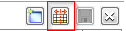
| 5. | Menu item → Tools → Compare |
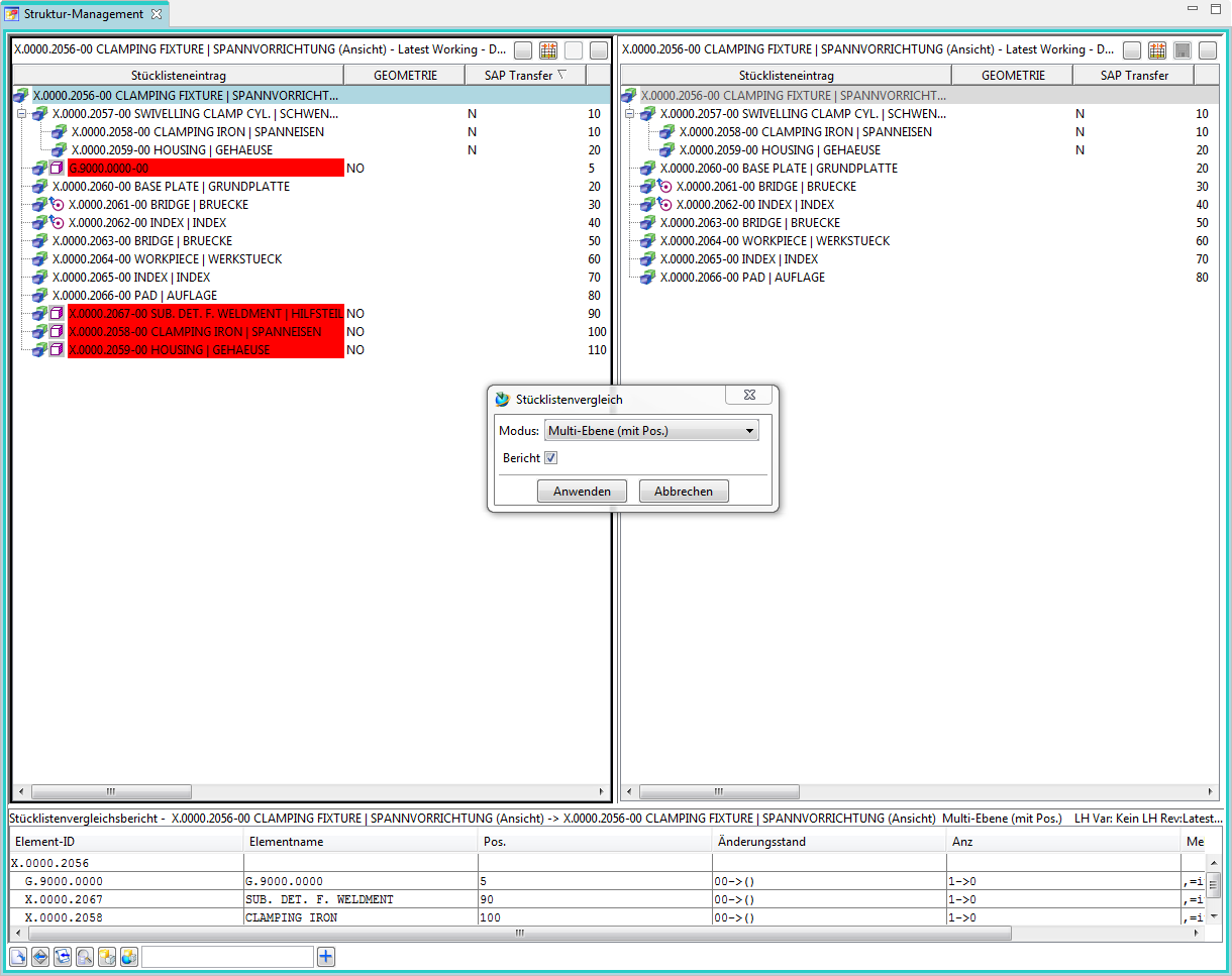
An example of a single-level comparison with a BOM comparison report:
At the end the comparison can be removed again in the menu → Tools → Delete comparison.
5.5 Working with "auxiliary parts" and non-geometric parts
5.5.1 Overview
This specification provides for a single integrated structure, i.e. both the “design view” and the “production view” must be able to be mapped consistently in this structure.
An essential aspect of this concept is the fact that in the previous PLM system Agile there is a separate design structure “document structure” and a product structure “article structure” and these must be merged into an integrated overall structure.
The differences in the use of the components are called “non-geometric parts” and “auxiliary parts”.
5.5.2 Non-geometric parts
Non-geometric parts are those that are not included in the design structure, but are nevertheless procured via the product structure. Examples are glue, oil, or text items.
The CAD system NX is inherently capable of hiding parts without geometry or marking them as “non-geometric”. For this purpose, the Occurence-Note “UG GEOMETRY” is set to the value “NO” at a revision in the BOMLine.
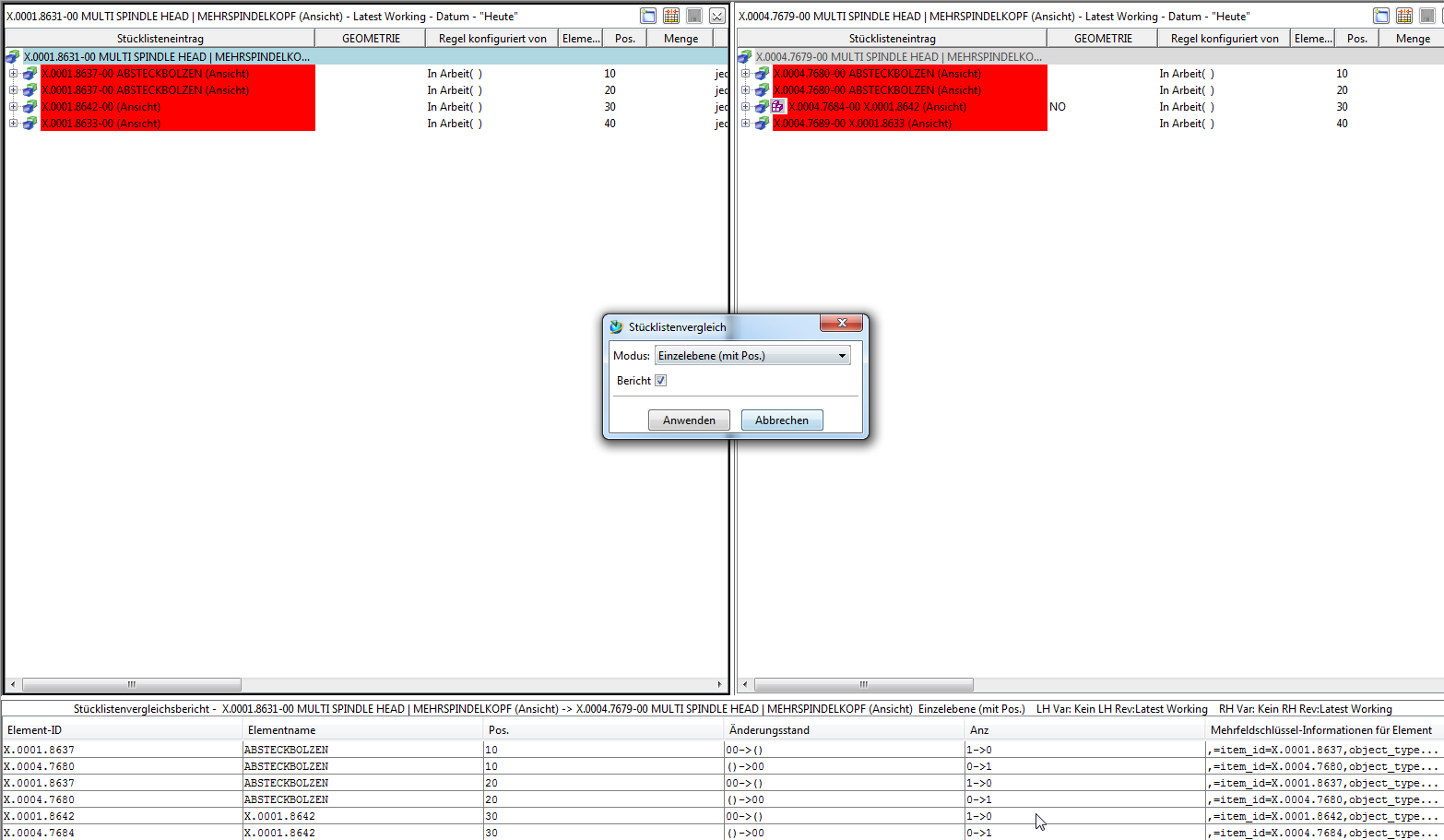
Example: The following assembly contains non-geometric parts (GEOMETRY=NO).

The representation in NX looks as follows:
5.5.2.1 Setting non-geometric components in NX
In NX a component can be marked as non-geometric via RMB → Properties → “Component is Non-Geometric”.

5.5.2.2 Setting non-geometric components in Teamcenter
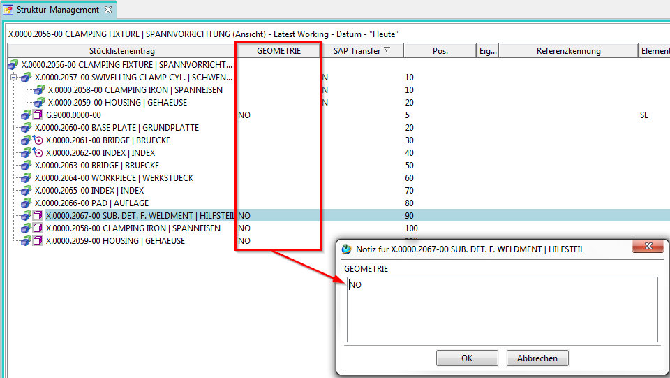
In Teamcenter a component can be set to non-geometric in the Structure Manager by setting the Occurrence Note “GEOMETRY” to “NO”.
5.5.3 "Auxiliary parts"
An “auxiliary part “ is a part in a bill of material that is not to be transferred to the ERP system (SAP). Usually, such parts are used to group parts together or they are built into the structure for functional reasons. In general, these parts have geometry, i.e. they are displayed in the CAD system and used in the CAD structure. By default, Teamcenter/NX does not offer the possibility to mark such parts as “non ERP-relevant”. Therefore, the Occurrence-Note “FFG4occSAPTransfer” is introduced, which makes it clear to the SAP interface whether this node (component or whole sub-assembly) should be flitted out during the SAP transfer.
5.5.3.1 Logic for the SAP transfer
If the value “N” is set, the corresponding node is not transferred, that is, the entire branch is filtered out, regardless of whether the nodes below it have set the SAP transfer flag or not. If the flag has no value, the node is transferred to SAP.

5.5.3.2 Marking "Auxiliary parts" in Teamcenter
In Structure Manager you can edit the value of the Occurrence Note by double-clicking on the corresponding column. Possible values are “N” or an empty field.
5.5.4 Display in the Structure Manager
In the Structure Manager, a structure can be filtered according to criteria. ClosureRules are used for filtering. In the preference ClosureRulesForBomExpansion those ClosureRules are defined, which can be used in the Structure Manager to display the structure. The structure itself is not changed.
5.5.4.1 Setting the view via the Closure Rule
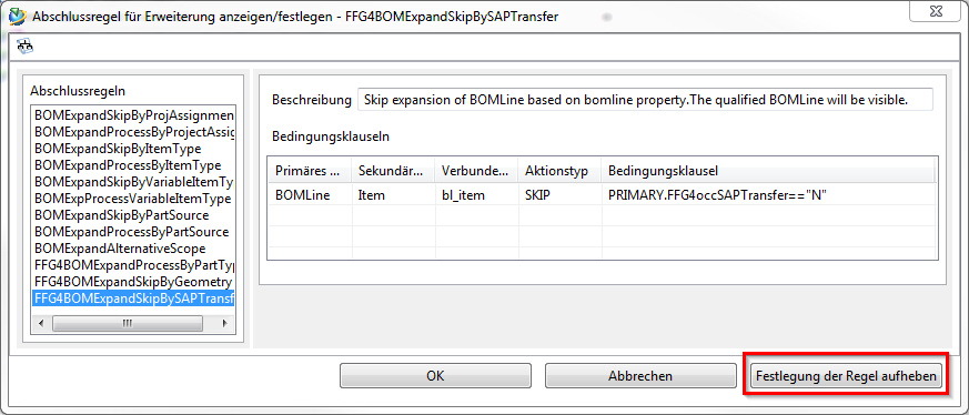
A view in the Structure Manager can be set as follows: Tools → “Set/display closing rule for enhancements “

The dialog for the closing rules opens:

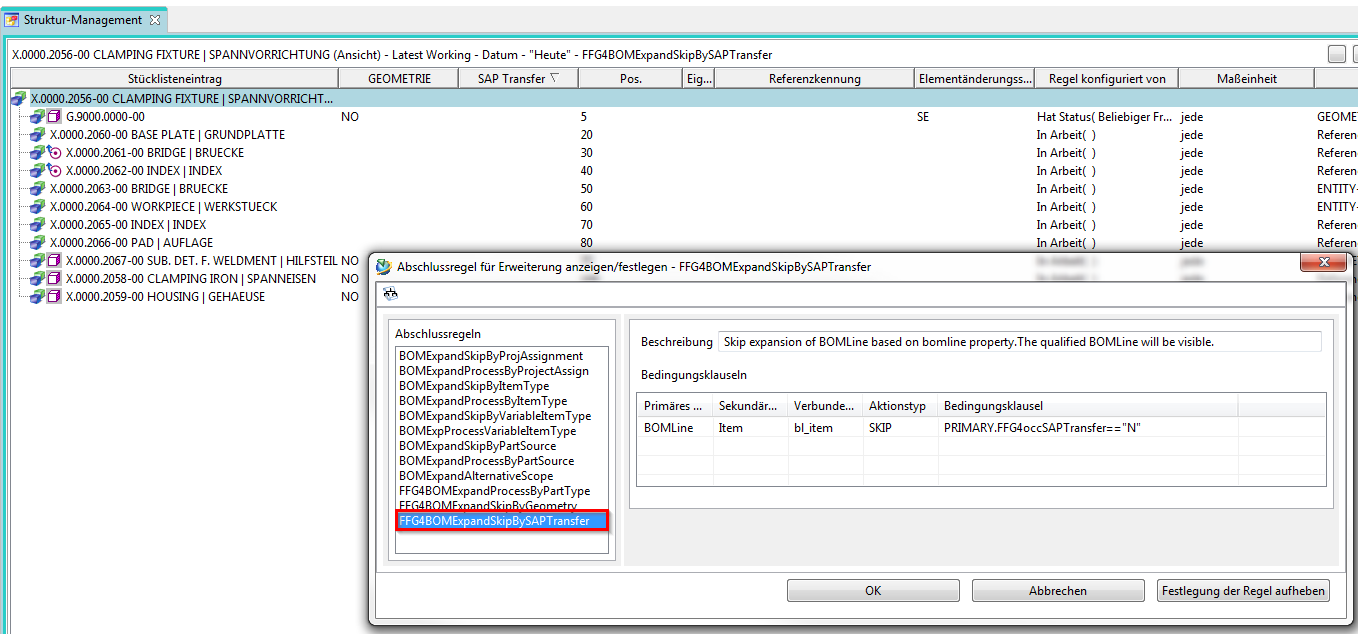
Select the desired rule and confirm it with OK.
The view is updated according to the rule.

To reset the view, press “Cancel rule definition” in the previous dialog.
5.5.4.2 Examples
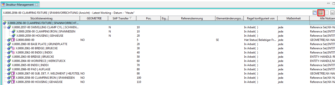
5.5.4.2.1 View of the unfiltered structure

5.5.4.2.2 Design view

5.5.4.2.3 SAP view
5.5.4.3 Comparison of the views
In the Structure Manager, design and SAP views can be displayed side by side and compared. To do this, first open a new window with the selected button.
Afterwards the Structure can be opened in the Teamcenter Navigator via RMT –> “Send to” –> “Structure Manager “ in this new window.

The comparison can be started via “Tools” –> “Comparison… “.
Example: Comparison of the entire structure with the design structure:
Example: Comparison of the entire structure with the SAP structure:

Example: Comparison of the design structure with the SAP structure:

Solid Edge
1. Solid Edge 2023 Update
Teamcenter Documentation
1. Overview
2. Teamcenter Basics
3. Working in Teamcenter
4. Working with CAD applications
5. Working with the structure manager
6. Workflows in Teamcenter
EPLAN - integrate2
1. Preamble
2. Function Description
3. Operating the Integration
4. Troubleshooting