User Tools
Table of Contents
3. Design
3.1. sketch preparation
3.1.1 Sketch section view
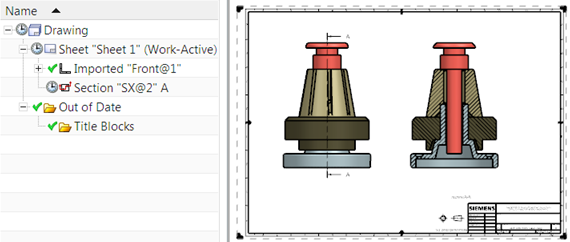
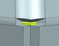
In the Sketch Task Environment application, you can view a sectional view of a part to better visualize its inner details and dimensions as you sketch. The sketch plane is automatically used as the section plane. You can also display a slice of your section view or automatically reverse the section view when you rotate your model.
Display a sectional view
 Cut Cut |
| To see the inside of your part on the sketch plane, use the Section command to display a section view of your part. In this example, the Sketch Emphasis command is used to highlight the active sketch. |
Splitting the section view into layers
 Slice Slice |
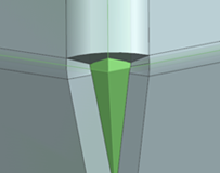
| To display a layer of your part when sketching, use the Layer (Slice) option. |
Reverse a sectional view
 Reverse cutting direction automatically Reverse cutting direction automatically |
| If you want to reverse the sketch intersection direction automatically when you rotate your model, use the Auto Reverse Section Direction option. |
Where can this function be called?
| application | sketch task environment |
| Menu ribbon | Register Home page (Home) → → Group Sketch → Section (Section) Home Tab → → Sketch Section Group → Layer (Slice)  } }Home Tab → Sketch Section → Auto Reverse Section Direction  |
3.1.2 Creating alignment constraint conditions
Use the Create Alignment Constraints user standard to control whether Horizontal Alignment  and Vertical Alignment
  are automatically determined when you create curves.
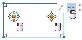
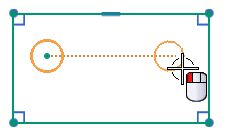
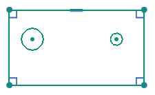
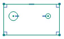
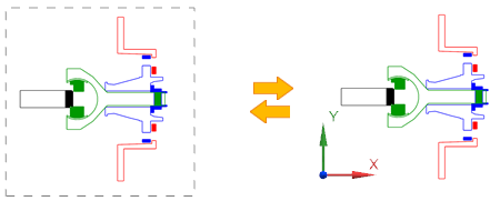
In this example, a second circle is placed to the right of the left circle. Note that the center of the second circle snaps so that it is aligned horizontally with the first circle. However, a horizontal constraint is only determined automatically if the user standard Create Alignment Constraints is set.
 |  |
 |  |
 Create alignment constraint conditions Create alignment constraint conditions |  Create alignment constraint conditions Create alignment constraint conditions |
If Create Alignment Constraints is enabled, you can manually disable alignment constraints in the Inferred Dimensions and Constraints dialog box. If the user default is disabled, the Horizontal Alignment and Vertical Alignment options are not displayed in the dialog box.
When is this function used?
You can control whether horizontal and vertical alignment constraints are automatically determined when you create curves. By default, the Create Alignment Constraints user standard is disabled and no alignment constraints are automatically determined during curve generation. In NX 11, the horizontal and vertical alignment constraints are automatically determined by default.
Where can this function be called?
| Application | Sketch |
| Prerequisites | The user standard Create Alignment Constraints must be activated. |
| Command Search | Determined Constraints and Dimensions |
| Position in dialog window | Horizontal alignment Vertical alignment |
3.1.3 Sketch highlighting
Use the Sketch Emphasis command to quickly identify the active part when you create a sketch in the assembly context in the Sketch Task Environment. This command enhances and replaces the Highlight Work Plane Emphasis command in the Sketch Task Environment, which, while paler in color for all objects that are not on the sketch plane, does not identify the active part.
 |  |
| Sket highlighting activated | Working level highlighting is activated |
When is this function used?
You can use this command to quickly see in which part you are creating a sketch. This allows you to avoid creating unintentional WAVE shortcuts and reliably select the correct active part before creating a sketch.
Where can this function be called?
| Requirement: | You must be in the Sketch Task Environment. |
| Command search: | Sketch highlighting |
| menu bar: | tab “home” → group “sketch → sketch highlighting |
3.1.4 Using multiple windows when creating sketches
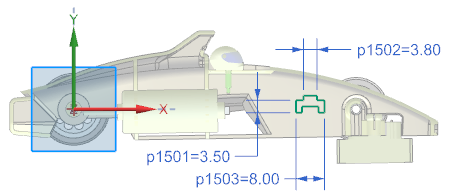
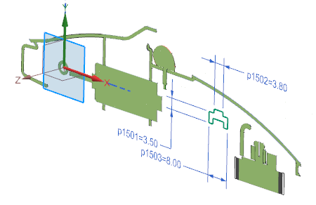
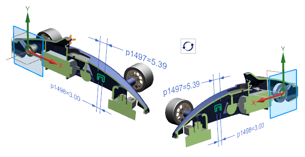
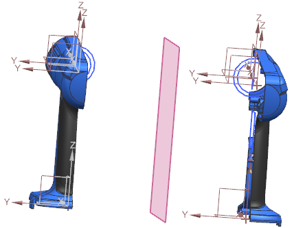
If you are working in the Sketch Task Environment and in Direct Sketch, you can now display multiple parts simultaneously in separate tab windows.
If the component you are editing appears in both windows, your changes are automatically applied to both windows.
In this example, a part on the left side and its parent assembly on the right side are open. You can view the updates to the part on the right as you create or edit the sketch.
If you create a sketch in multiple tab windows, you can do the following:
- Create components from the assembly in a separate window. With this method, you can only display the new component without manually hiding the other components.
- Reference a component to quickly create a similar sketch in a separate window because both components are displayed simultaneously.
- Change components in a single window. The changes are automatically reflected in all windows that display this component.
Note:
If you create the sketch directly in Construction, you have the following options:
→ You can hold and drag the mouse wheel or use the Spaceball to switch to another tab window.
→ You can quickly disable the sketch by clicking in another tab window.
Where can this function be called?
| Application: | Construction |
| Prerequisite: | You must have several parts open. |
| Menu ribbon: | File tab → Window → Window layout → Select a command based on the desired arrangement and the number of parts to be displayed simultaneously |
3.2. construction
3.2.1 New construction commands
3.2.1.1 KSYS print
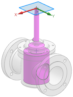
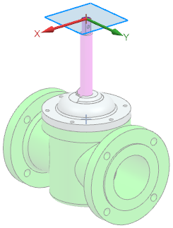
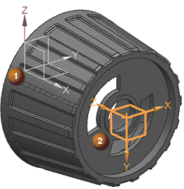
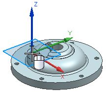
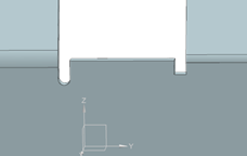
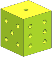
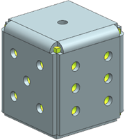
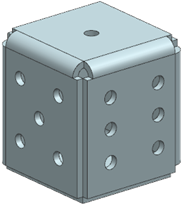
When designing a model, you can use the new Print CSYS command to create a coordinate system that defines the print direction that will be used later in 3D printing.
You can manually define the orientation of the Print KSYS command or you can leave it to NX to suggest an orientation that will cause significant smoothing of the part when it is printed. The result is a new KSYS shape element that is positioned so that the part rests on the XY plane and the creation direction is aligned in the +Z direction.
 |
| (1) Absolute reference KSYS used in model building (2) KSYS for printing is aligned to smooth the part for printing |
You can now use the following commands to add a print coordinate system to a model:
- Check clamped supports
- Check maximum overlap angle
- Check printable volume
In these cases, NX adds a new KSYS to the model for printing and determines its placement using the currently specified design plane KSYS.
Where can this function be called?
| Application: | Construction, manufacturing |
| Command Search: | KSYS print |
3.2.1.2 Body by equation
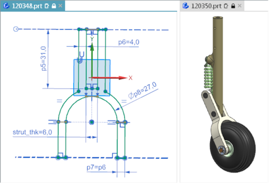
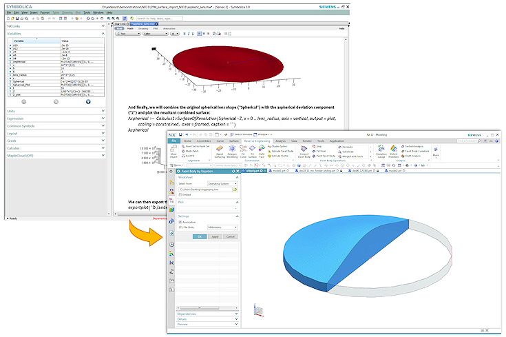
Use the Body by Equation command to import complex, mathematically defined surfaces into NX as convergent facet bodies from Symbollica.
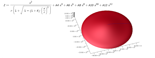
The new NX form element is connected to the corresponding Symbolica output worksheet and the STL output file of the 3D plot. Each time the Symbolica worksheet is changed, the linked NX facet body is updated.
You can import Symbolica output worksheets from the following locations:
- A directory in the operating system.
- A Teamcenter position
- A Symbollica worksheet previously embedded in the NX part file.
When is this function used?
Use the Body by Equation command when you need equation-controlled bodies and surfaces in applications that integrate the laws of physics into their constructions. Examples include the space and automotive industries, shipbuilding, and optical industries.
- By creating equation-controlled bodies, there is no need to use techniques that can lead to errors, e.g. cutting and longitudinal direction or other non-associative, approximate development techniques.
- You can use the Body by Equation command in conjunction with Converging Construction to use equation-controlled bodies directly in NX Construction. This results in improved accuracy and reduced design time.
Where can this function be called?
| Application: | Construction |
| Prerequisite: | You must have access to Symbollica or Maple (.mw) worksheet files. |
| Command search: | Body by Equation, Symbolica |
3.2.2 Command, tool and selection - extensions
3.2.2.1 Defining print marks
When constructing a model, you can now use the Text command to define areas as print marks that determine where text markers, such as serial numbers or date codes, should be applied in the later 3D printing process.
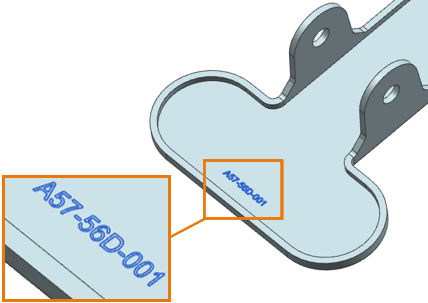
The resulting Print Mark text form element can be aligned and has an attribute that identifies it as special dynamic text. You can use asterisks (*) as placeholders for variable text, which is replaced by single characters or digits in the string during additive manufacturing.
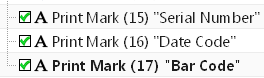
Print marks in Parts Navigator
- The generated form element displays the same or other text form elements in the Part Navigator, but is not labeled with text, but with print mark.
- To distinguish between print marks, you can assign a unique usage label to each of them.
Where can this function be called?
| Application: | Construction, manufacturing |
| Prerequisite: | Define the user standard Show Additive Manufacturing-specific Dialog Items in Modeling Commands. |
| Command search: | Text |
| Position in the dialog window: | Group Print Mark Settings |
3.2.2.2 Grid extensions
The Lattice command has been extended as follows:
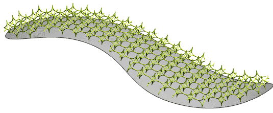
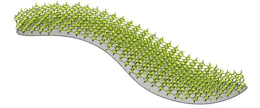
You can now create a Conformal Graph grid.
A Conformal Lattice has the following properties:
- Follows the contour of a face or solid.
- Can be offset from the selected face or body.
- Can consist of multiple layers.
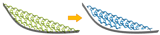
If you create a Unit Graph grid, you can now do the following:
- Using the new Remove Disconnected Lattice Potrions option, remove small, unconnected lattice areas and retain only the largest body.
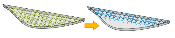
- Use the new Remove Rods at Selected Faces option to remove all members from the grid graph that are connected to the grid at only one end and touch a single one of the selected faces of the boundary body.
Where can this function be called?
| Application: | Construction |
| Command search: | Grid |
3.2.2.3 Construction support for multiple windows
The Design application has been enhanced to allow you to work more efficiently across windows:
- Undo/Redo - The Undo and Redo commands are available on all tabs of a multi-screen session. They perform the correct action for the corresponding part on the respective tab. When you switch between tabs of parts and switch applications, the Undo and Redo commands still retrieve the corresponding tab and command history and perform the correct action.
- Switch Application - When you switch to another window, NX automatically starts the application that was running for the part. Example: When you switch to a window that contains a drawing, NX automatically launches the Drawing Creation application.
- Selecting Objects - When using a Design command, you can only select objects in the active window.
Where can this function be called?
| Application: | Construction |
3.2.2.4 Parts navigator extensions
If you work with different parts across windows, the Part Navigator now retains the following settings and displays them for each part as soon as the corresponding window becomes active:
- The Column Sorting
- The extended or reduced state of the nodes
- The scroll position
- The Timestamp Order status: Enabled or disabled.
- The active filters
The following settings are not retained for each part and are identical across all windows until they are changed:
- Properties of Part Navigator
- Column configuration
When is this function used?
When switching between part windows, the Part Navigator retains its purpose so that you can simply continue working with that part from where you left off.
Where can this function be called?
| Application: | Construction, Shape Studio |
3.2.2.5 Expressions - extensions
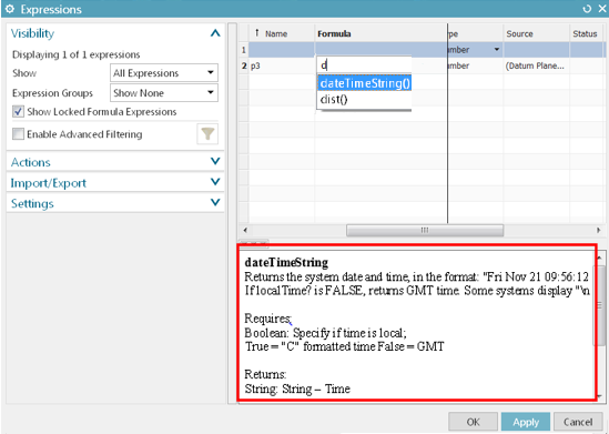
The Expressions command has been enhanced with a new Help Information window at the bottom of the dialog. When you select embedded functions, the Help Information window allows you to conveniently display descriptions of the function, the required input parameters, and the output type.
Where can this function be called?
| Application: | Construction, assemblies |
| Prerequisite: | The Expressions dialog box must contain an embedded function in a Formula cell. |
| Command search: | Expressions |
3.2.2.6 Cross-sections - Extensions
The Section Surface command has been extended so that when you create a section with the specified type and mode, the following applies:
- Conical type with Rho mode - No excessive oscillations in the guide direction are generated if the Split Along Guides option is selected.
- Type Circular with Two Point Radius mode - you can now create alternative solutions.

- Cubic type with Fillet Bridge mode - NX adds poles only when needed to achieve the desired consistency. In addition, handles are added to the defining edges of the surface so you can adjust the surface interactively. In the example below, the surface on the left has consistency G1 (G1 ) on both sides. The surface on the right side shows the pole structure when you change the consistency of the right side to G2 (G2).
- Type Linear with Point Angle mode - processes are created and updated faster.
- Type Circular with Two Point Radius mode - Fewer poles are generated and the generated poles are distributed more evenly.
Where can this function be called?
| Application: | Construction |
| Command search: | Interfaces |
| Position in the dialog window: | Groups type and mode |
3.2.2.7 Curve direction of extrusion cut
Several commands that support curve selection have been extended as follows:
- The Reverse Direction option has been added to the Curve Selection options.
- When you select a curve, an arrow in the Graph window indicates the direction of the intersection curves. You can change the direction of the curve by double-clicking the arrow or by clicking Reverse Direction in the dialog box.
Where can this function be called?
| Command search: | →Extrude →Offset curve →Offset curve in area →Project curve →Sectional area →Divergent extrusion →Offset curve |
| Position in dialog window: | Options for curve selection |
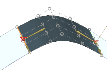
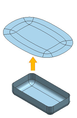
3.2.2.8 Control of twisting during surface unwinding
New options are available that allow you to control the torsion that can occur when unfolding certain 3D surfaces.
Constraints Group
Unwind with (Flattening with) = Fixed Elements
You can unwind with fixed elements that you select from the smoothing output surfaces. The fixed elements remain fixed during the unwinding process.
Fixed elements can correspond to one of the following object types:
- Surfaces
- Edges
- Snap points
Fixed elements must be on a common plane (coplanar) and form a single, connected component (points must only be coplanar).
 |  |
| Flattening with = None | Reduced twist when flattening with = Fixed Elements, wherein a face is selected as the fixed element. |
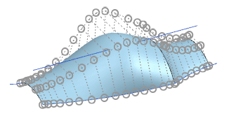
Group edge
Allows you to select surface edges or curves on the initial surfaces for use as edges. During the unfolding process, the starting surfaces are “broken” along the edge and curves to minimize distortion.
Depending on the underlying geometry, twists may still occur.
- Multiple edges are allowed when selecting, whether or not they are connected.
- Edges must always be connected to the outer boundary. A contour of internally connected edges is permissible if at least one of the associated ends is connected to the outer boundary.
An internal edge is not allowed if it is not connected in any way to the outer boundary (e.g. with a column).
 | 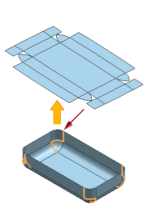 |
| No edge (Rip Edges) selected | Four edge contour trains selected as edge (Rip Edges) |
Outside boundary
The new Diagnostics group has been added to the dialog window, which contains the existing Distortion Map options.
Where can this function be called?
| Application: | Construction, Shape Studio |
| Command Search: | Smooth and Form |
3.2.2.9 Delete subordinate form elements - extensions
The Delete Child Features option has been enhanced with the new Ask setting so that you can set NX to prompt whether you want to delete child form elements each time you delete an item. In earlier versions, you could only predefine Yes or No for all child form item deletions. You could not choose to be asked every time you delete a form item.
You can set Delete Child Features in your User Defaults or Ask in your Design Preferences. The User Default setting determines the default setting for this option in your Design Preferences.
Where can this function be called?
| Application: | Design preferences |
| Position in the dialog window: | edit tab → Delete subordinate form elements list |
Delete a selected form element:
| Menu: | Menu → Edit → Delete |
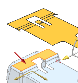
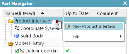
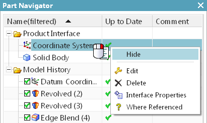
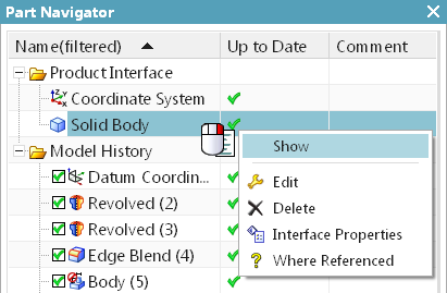
3.2.2.10 Product interface - extensions
You can now view, hide, and create product interfaces directly from the Part Navigator using the new Show, Hide, and New Product Interface context menu commands.
 | ||
 | ||
 |
3.2.2.11 Optimize the curve
The default setting of the Optimize Curve option included in Customer Defaults and Modeling Preferences has been changed to On.
Where can this function be called?
| Command Search: | Construction Preferences → User Defaults |
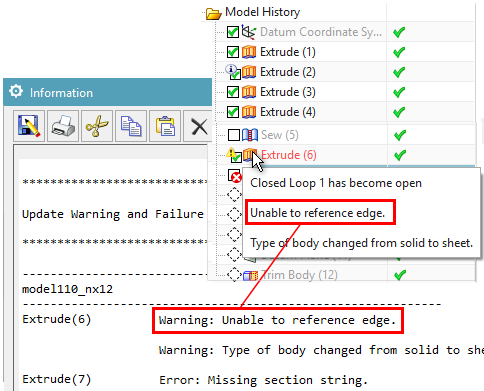
3.2.2.12 Warnings about missing references
Use the new Warn on Missing References design preference to specify whether warnings about missing references should be displayed in the Update Warning and Error Report information window and as tooltips in the Part Navigator.
A reference is missing if an object on which a form element depends is suppressed or removed.
The following example displays warnings about a missing reference edge of an extruded shape element.
The default setting Warn on Missing References and the existing default setting Make Current Feature on Error together replace the function of the Edit During Update (EDU) dialog box that is no longer used.
The default setting Warn on Missing References is disabled by default. It is not recommended to use it when performing a general solid construction.
Tip:
The default setting Warn on Missing References is also available as a user standard.
When is this function used?
You can receive warnings about missing references when you update a model.
Where can you call this function?
| Application: | Modeling, Shape Studio |
| Prerequisites: | To display tooltips in the Part Navigator, the Show Tooltips on Dialog Options check box must be selected in the Customize dialog box on the Icons/QuickInfos (Icons/Tooltips) tab in the Tooltips group. To stop updating or form element playback of a part if an error occurs and to specify the incorrect form element as the current form element, select the Make Current Feature on Error check box on the Update tab of the Modeling Preferences dialog box. To display a report on warnings and form element errors during an update, select the Generate Warning/Failure Report after Update check box on the Update tab of the Modeling Preferences dialog box. |
| Command Search: | Construction Defaults |
| Position in the dialog box: | Refresh tab → Check box Warning if references are missing |
3.3. assemblies
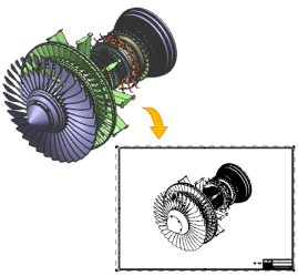
3.3.1 Retaining components displayed in a model view
The Show Components in View command has been enhanced with the new Maintain Components Shown in View option, which allows you to retain the display of your current model view. If set, the displayed components are preserved when you set the option, and any new component that is added to the assembly is automatically hidden in this model view.
In other model views, the new components you add are still displayed.
Where can this function be called?
| Application: | Equipment |
| Requirements | At least one component in your current model view must be hidden by the Hide Components in View command. |
| Command Search: | Show components in view |
| Position in dialog box: | Group Components to display → Check box Keep components displayed in view |
3.3.2 Adding components - extensions
The Add Component command has been enhanced as follows to simplify the workflow for adding parts to your assembly:
- The Component Anchor option now allows you to create custom positions to place components.
- The Assembly Location option lets you use the Snap placement setting to select a face on an assembly to place a component.
- The Move Component and Assembly Constraints dialog options have been integrated into the Placement Group.
- The component preview can be displayed in the graphics window in addition to the Component Preview window.
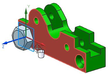
Other anchor points
If you added a component in previous versions of NX, you could only select the absolute origin as the anchor point. Using the Product Interface command, you can now specify additional points as selectable anchor points. This gives you greater flexibility in adding components in the correction orientation and speeds up the component placement process.
Catching components on surfaces
Use the Snap setting for the assembly position to place a component on existing surfaces in the assembly. This is similar to creating a sketch. The position of the mouse pointer and the orientation of the assembly determine the area on which the component is placed and the orientation of the component relative to the assembly.
Placement options for moving and defining with constraint conditions
In previous versions of NX, if you clicked Move or By Constraints in the Placement group after selecting an origin point in an assembly, the Move Component or Assembly Constraints dialog box opened. Now the Move Component and Assembly Constraints dialog options have been integrated into the Add Component dialog so that you can do the following directly from the dialog:
- Use the same Move Component options to place the component.
- Select and create constraint types.
- Remove all constraints by clearing the Keep Constraints option.
This integration allows you to access other options for adding components without canceling the constraints you created for the component you want to place.
Where can I access this feature?
| Application: | Equipment |
| Command Search: | Add Component |
3.3.3 Loading options for assembly extensions
The Assembly Load Options command has been enhanced to make it easier to specify how a component is loaded and displayed.
In the Scope group, the Use Partial Loading and Use Lightweight Representations check boxes have been replaced by the Option list with the following settings:
- Fully loaded (Fully Load)
- Partially Loaded
- Fully charged - Lightweight display (Fully Load - Lightweight Display)
- Partially Loaded - Lightweight Display - Lightweight Display
Where can this function be called?
| Application: | Equipment |
| Command search: | Load options for assemblies |
Minimum loading of components stored in Teamcenter
Use the new Minimally Load - Lightweight Display option to load and display assembly components with lightweight representations. This option loads less data than the Partially Load - Lightweight Display option and uses multiple processors to improve loading performance. The assembly is displayed early in the loading process so that you can set up your scene while the components are loading, such as zooming, panning and rotating the view, and hiding or displaying components.
Controlling the loading status of components
If you use the Minimally Load - Lightweight Display option, you can use the Pause, Play and Stop commands to pause, resume and stop the loading of components. The control buttons are now larger and appear in the lower right corner of the active window.
 | |
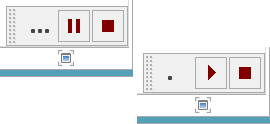 |
When is this function used?
Minimal component loading requires less loading time than other loading options and is useful when working with large assemblies in design, visualization, geometry calculation, and drawing creation workflows.
Where can this function be called?
| Application: | Equipment |
| Prerequisites: | You must use Teamcenter Integration for NX and load components from Teamcenter 11.3.0.1 a01_patch5, 11.4.0.5 or higher. This option works best when you load components stored in NX 9 or later. |
| Command search: | Load options for assemblies |
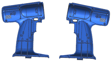
3.3.4 Reflection of components
If you need both a left and right version of a component, you can add the component to the assembly and then reflect it to create the other version. The reflected component is a new instance of the original component. No new part file is created. You can also reflect subassemblies or multiple components.
Editing a Reflected Component
The reflected and non-reflected component instances refer to the same part file, so that the geometry is always identical in all instances. Since a reflection transformation has been applied to a reflected instance, the entire geometry is reflected in it. If you edit the geometry in the original component, the changes appear in both the reflected and non-reflected component instances.
Since you cannot make a reflected component instance an active part, you cannot edit the geometry directly in the reflected component instance.
Preparation of reflected components for subsequent processes
Since a reflected component is an instance of an existing component, you must ensure that subsequent processes, including production, can recognize which instances are reflected and which instances are not. For example, you can assign a unique component name to a reflected component if you can use component names to distinguish between reflected and non-reflected instances in your company³s processes.
When is this function used?
You can create a reflected component instead of a mirrored component if you do not want to create a new part file for the new component instance.
Where can this function be called?
| Application: | Equipment |
| Command search: | reflect component |
3.3.5 Mirror assemblies - extensions
If you mirror an assembly, you can now also mirror the absolute origin of the assembly. In earlier versions, the same absolute origin is used for a mirrored assembly as for the source assembly.
A mirrored absolute origin is in the mirrored position, but has the same orientation as the absolute origin of the source.
With the Mirror Absolute Origin Location user standard, you can control the default setting of the Mirror the absolute origin location of all mirrored assemblies or components option.
Where can this function be called?
| Application: | Equipment |
| Command search: | Mirror assembly |
| Position in dialog window: | Assistant: Mirror assemblies → Select page Layer → Mirror position of the absolute origin of all mirrored assemblies or components |
3.3.6 Sorting in the Assembly Navigator by data type
When you sort data in the Assembly Navigator by clicking the Report Property column, NX now sorts the data by its data type, such as alphanumeric sorting for strings, numeric sorting for numbers, or date sorting for dates.
Previously, data in the Report Property column was sorted alphabetically.
Where can this function be called?
| Application: | Equipment |
| Prerequisites: | The HD3D Visual Reporting tool must be enabled. |
| Unit Navigator: | Column Report Property . |
3.4. drawing creation
3.4.1 Support of the drawing creation for the display of several parts
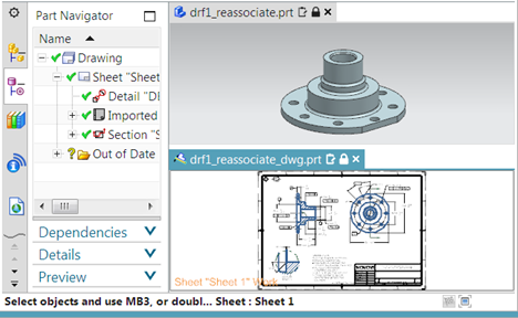
You can now open multiple tab windows when working with drawings and master parts and view them separately or all at once in organized groups.
You can use tab windows to do the following:
- Work simultaneously in the master model and drawing without changing the displayed part.
- Work on specific sheets in multiple drawings. This can be the case if you want to create drawing test documents or display drawing differences between several revision states of the same part.
- Quickly cut, copy, and paste objects between drawings.
- Visualize the effect of changes to the custom master icon in drawings that contain instances of the master icon.
When working in an extended drawing view, you must first undo the view extension before you can switch to another window.
When will this function be used?
You can work in the Master model and in the non-Master drawing part at the same time. This is especially useful if you want to immediately view and match differences in the drawing caused by changes in the 3D model.
Where can you call this function?
For more information on viewing and working with multiple parts in the same NX session, see Viewing designs in multiple windows.
3.4.2 Drawing creation support for minimally loaded assemblies
The Drawing Creation application supports the use of the new Minimal Load - Lightweight Display loading option, which is a fast lightweight loading option from NX 12.0.2.
If you use this option, only solids in the active Reference Set are loaded and displayed as faceted geometry. All other part geometries and part attributes, as well as all inactive Reference Sets and components, remain unloaded until you manually load them. This can affect the display of your drawing.
For more information, see Effects of Loading Options for Assemblies in Drawings.
When is this function used?
Use the Load Minimal - Lightweight display loading option if you want to load a very large assembly consisting of thousands of components more efficiently and quickly.
Where can this function be called?
| Command search: | Load options for assemblies |
| Position in dialog window: | Group Scope → List Option → Load minimal - Lightweight display |
3.4.3 Improvement in form and position tolerances
The Feature Control Frame command has been enhanced with new indicator options so that you can add the following indicators to individual tolerance frames:
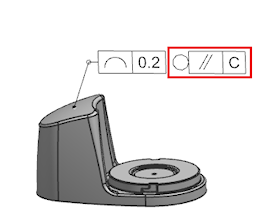 Collection level display | 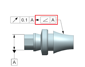 Display directional form element |
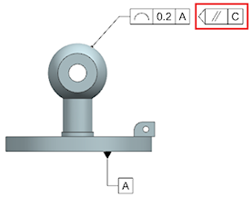 Cut plane display |
|
When is this function used?
You can add the latest standards-compliant form and position tolerances to your part.
Where can you call this function?
| Application: | Drawing and PMI |
| Prerequisites: | You must specify the user default indicator group to display. |
| Command search: | Form/position tolerance frame |
| Position in dialog window: | Group Frame → Subgroup Indicator → List Type |
3.4.4 Unequally distributed tolerance modification factor in shape / position tolerances
The Feature Control Frame command has been enhanced with the new UZ option, which specifies an unevenly distributed tolerance zone.
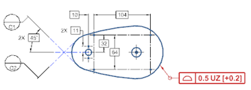
When is this function used?
You can add “Form/Location”, which is compatible with the latest ISO and DIN standards, to a part.
Where can this function be called?
| Application: | Drawing and PMI |
| Command search: | Form/position tolerance frame |
| Position in dialog window: | Group Frame → Subgroup Tolerance → Subgroup Tolerance Modification Factor → Check box UZ |
3.4.5 Angle dimensioning
The Angular Dimension command has been enhanced with the Directed dimension type so that you can create dimensions directed by angle. A directional dimension is a dimension that specifies the direction of a measurement and applies the entire tolerance to the second object.
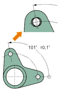
When is this function used?
You can capture additional design information by dimensioning the shape elements in your model. For example, the information captured by an angle PMI dimension can be used in downstream applications such as tolerance analysis and test applications.
Where can this function be called?
| Application: | Drawing and PMI |
| Prerequisites: | You must set the Enable Dimensioned Dimensions drawing preference before creating the dimension. |
| Command search: | Angle dimension |
| Position in dialog window: | Group References → List Dimension type → Aligned |
3.4.6 Dimensioning and Labeling - Extensions
| option through bore text | |
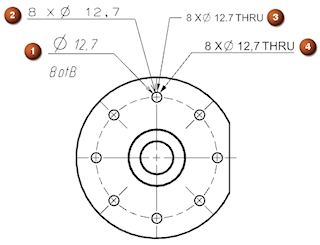 | You can specify the text string that represents the depth in a hole callout for a through hole. The drafting standard associated with your part, such as ESKD (1), JIS (2), ASME (3), and ISO (4), determines whether a default text string exists for the preset. |
| Show default zero at baseline | |
 | You can automatically display zero for ordinate dimension baselines. |
| Default value center dimension line | |
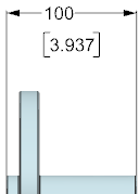 | You can center a dual dimension vertically on the dimension line. |
3.4.7 Limiting and fitting tolerances for hole and thread callouts
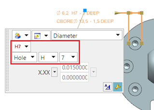
You can now apply bounding and fitting tolerances to callouts for the following:
- The diameters of general, drill size, and screw clearance holes.
- The inside, outside, and tap diameters of taps.
- The inside and outside diameters, pilot diameters, and shank sizes of symbolic inside and outside threads.
When you apply a boundary and fitting tolerance to a hole callout, the entire dimension above or inside it is displayed with the dimension line. You cannot apply the Split by Dimension Line setting to the dimension to display it both above and below the dimension line.
When will this function be used?
You can properly dimension supported hole types that require boundary and fitting tolerances.
Where can you call this function?
| Application: | Drawing and PMI | |
| Graphics window: | When creating or editing a hole callout → Field for dimension format → Dimension type list → Diameter, diameter for flap countersink or taper countersink diameter → Tolerance type list → Limits and fittings |
3.4.8 Hole callouts with double dimensioning
You can now create double-dimensioned callouts for :
- The diameters and depth parameters of general, drill size, and screw clearance holes.
- The diameter, depth, thread depth and pitch parameters of the tapped holes.
- The diameter, pitch, length, pilot hole diameter and shank sizes of symbolic internal and external threads.
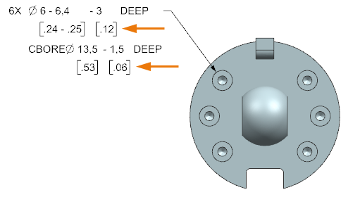
When you create or edit a hole dimension, you can set the Show Dual Dimension option for all supported parameters of the hole dimension. Prefix (diameter symbol) and suffix (depth text) for a hole diameter are displayed only for the primary parameters of the dimension.
When is this function used?
You can correctly dimension hole types that require a double dimension format.
Where can you call this function?
Creating and Editing a Hole Callout
| Application: | Drawing and PMI |
| Graphics window: | When creating or editing a hole callout, select the scene dialog → Dimension Type List → Diameter, Depth, Diameter for Countersink → Countersink Depth, Countersink Diameter, Countersink Depth, Countersink Depth, or Length → click Text Settings |
| Position in dialog box: | Text Settings dialog box → Node Double → Group Format → check box Show Dual Dimensions |
You now have greater control over the shapes of balloon symbols. You have the following options:
- You can edit the existing shape of one or more balloon icons.
- You can set the default balloon shape.
Where can this function be called?
Edit the shape of an existing balloon symbol
| Application: | Drawing |
| Graphics window: | Double-click on an existing balloon icon |
| Position in the dialog window: | Typlist |
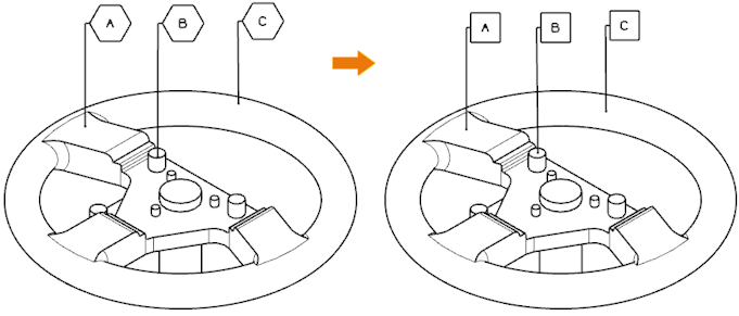
3.4.10 Support for model points in drawing view
The Include Model Curves drawing preference has been enhanced to extract construction points associated with the model and permanently display them in the Exact and Smart Lightweight drawing views. The construction points must be included in the Reference Set used to create the drawing view.
Construction points in the Reference Set used to create a drawing are now permanent objects in the Exact and Smart Lightweight drawing views. If the master model geometry is unloaded or not loaded in the NX session, the labels and dimensions associated with the construction points are not displayed as retained.
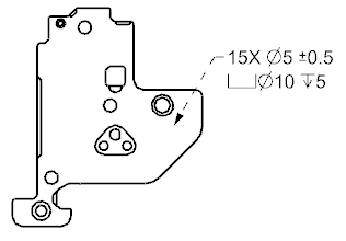 | 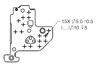 |
| former NX version | NX12 |
When is this function used?
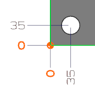
You can quickly extract construction points to specify meaningful areas in a drawing view without having to specifically load the linked model geometry. For example, you can specify the center of a large number of holes or identify areas on the model to associate important manufacturing information.
Where can you call this function?
| Application: | Drawing creation |
| Prerequisite: | * The points must be included in the reference set used in the drawing view. |
3.4.11 Cutting components - extensions
The function of the intersection component has been extended as follows:
You can now use any combination of uppercase and lowercase letters if you add the SECTION-COMPONENT attribute to a component, part instance, or object in the part. In earlier versions, the attribute of NX was ignored when a combination of uppercase and lowercase letters was used in the attribute name.
When the SECTION-COMPONENT attribute is changed for an object, all drawing views that contain the object are marked as obsolete.
In earlier versions, corresponding drawing views were not always marked as obsolete.
For more information on section objects in section views of drawing creation, see the Drawing Creation Help in the Section on Section Component Attribute.
Where can this function be called?
Setting the attribute for a specific part
| Application: | All NX applications |
| Menu ribbon: | File tab → Properties |
| Command Search: | Displayed Part Properties |
| Menu: | In the Displayed Part Properties dialog box on the Attributes tab in the Context group, the Interaction Method must be set to Traditional. |
| Position in dialog window: | Part Attributes group → DB Component Instance node → SECTION-COMPONENT (SECTION-COMPONENT) |
3.5. routing
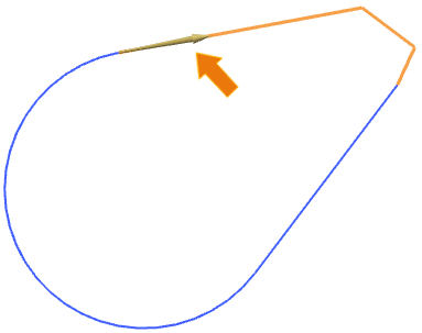
3.5.1 Spline path extensions
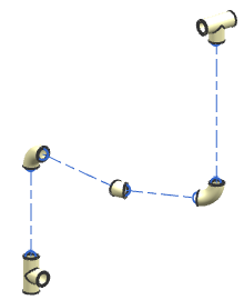
The Spline Path command has been enhanced with improved tangent settings for spline points. New options for tangent management are available when creating or editing spline paths. In addition, you now have a greater degree of flexibility in assigning tangency at specific spline points.
Automatic tangent setting when generating spline paths
The option Create Tangency between Splines is still available. This allows you to selectively apply or omit tangency at coincident spline points or between a spline end point and a linear end point when creating a spline path. When you create the spline path, you can enable or disable this option at any time to control the automatic creation of tangency at a specific point.
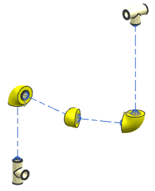
Display dynamic tangency
If you set the Create Tangency between Splines option, NX dynamically applies tangency to the spline segment when it is created. This becomes obvious after you have specified the second spline point along the path. If the spline ends at another spline or linear end point, you can click Apply or OK to update the last spline point so that it is tangent to the adjacent object.
Controlling the Tangency Between Splines
 |  |
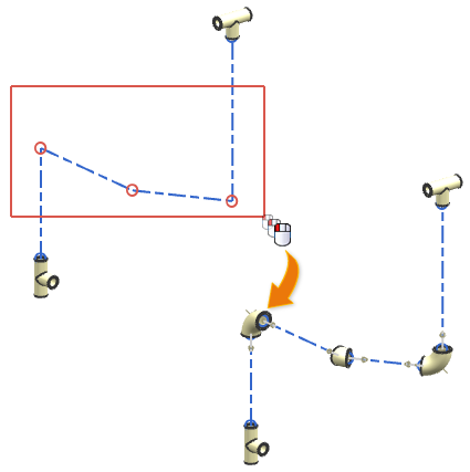
Once you have created a spline path, you can use the new Assign Tangency and Remove Tangency context menu commands to assign or remove tangency at any spline point. The spline path is automatically updated to reflect the tangent condition you selected.
When is this function used?
Tangent management allows you to control and change the shape of a spline path.
Where can you call this function?
Specify automatic generation of tangency during generation of spline paths.
| Application: | Routing |
| Command search: | Spline path |
| Position in dialog window: | Group Settings → Subgroup Constraint Settings → Check box Create tangency between splines |
Adding or removing tangency at existing spline points
3.5.2 Bending radius table
If you assign corner RCPs using the Assign Corner command, you can now access bend radius data controlled by a spreadsheet that is larger than the data available in a traditional bend table text file.
The Bend Radius Table Spreadsheet File user standard allows you to refer to a specific bend radius calculation file. This eliminates the need to manually select from one or more bend radius tables when assigning a bend radius to a path corner.
If you have imported the spreadsheet data from the Bend Radius Table, the data is displayed in a tabular format within the Assign Corner dialog box when you set Method to Bend Radius Table.
When will this function be used? Using a spreadsheet-based bend radius table, you can select a range of attributes from a single data source. For example, you can specify a bending radius based on a stock allowance, a specific machine setting for bending, and any attribute available for the stock size for your corner. The spreadsheet data can be managed by a system administrator. Where can this function be called?
| Application: | Routing |
| Requirement: | The path must be assigned to the allowance. |
| Command Search: | Assign Corner |
| Graphics window: | Click with the right mouse button on a corner RCP → Assign corner |
| Position in dialog window: | Group Corner → List Method → Bending radius table |
3.5.3 Place several contra-angles
The “Routing - Mechanics” application has been enhanced to simplify the placement and alignment of multiple contra-angles on a path. If you have specified an angled connector, you can select multiple corner RCPs for angled piece placement individually or using the multiple selection method Rectangle, Lasso and Circle.
You can place multiple standard and cut elbows on path corners before or after applying the allowance and distance reservation.
Apply standard oversize
If you place multiple contra-angles, use the new Apply Default Overstock option to apply default oversize for isolation.
 |  |
Where can this function be called?
| Application: | Routing - Mechanics+Routing Piping and Tubing |
| Command search: | Place multiple contra-angles |
3.5.4 Routing attribute source categories
Routing attributes are now grouped into specific attribute categories so that NX can identify the source for the attribute. These sources include the application view files (APV files), the default routing subfamilies, and the routing application when the object is instantiated. Routing attributes are displayed in the Component Properties dialog box.
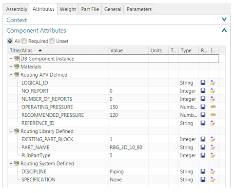
In this example, the PART_NAME (PART_NAME) attribute is derived from the Routing Part Library and the DISCIPLINE (DISCIPLINE) attribute is created by the routing application when the part is created. The following attribute categories are used for routing attributes:
- Routing APV-defined
- Routing library defined
- Routing system defined
These attribute categories allow NX to identify the source of a routing attribute and help determine which attributes should be copied between objects when performing operations such as Place Part, Replace Part, Edit Stock or Unify Path.
Editing Routing Attributes
To prevent accidental changes or deletions of critical routing information, most routing attributes are locked and cannot be edited. Some non-critical routing attributes can be edited directly in the Component Properties dialog box.
Rename Attribute Source Categories
Routing attribute categories are defined in the Attributes_Source_Category_Names section of the APV file for Routing - Electrical and Routing - Mechanical. If you prefer different category names, you can manually rename them in the APV file. However, if you edit the names, you must ensure that the category names are unique so that the attribute sources in the part can be identified. It is recommended that you avoid frequent renaming of categories, as invalid names can lead to unexpected results.
| Application: | Routing - Mechanics+Routing Piping and Tubing |
| Assembly navigator: | Right-click on a part or oversize → Properties |
| Position in the dialog window: | Tab Attributes |
3.5.5 Updating of stock measurement definitions
Refresh stock definitions provides the ability to refresh a definition of the stock allowance, such as cross-section, descriptor characteristics, or other attributes taken from a part table or Teamcenter classification.
When is this function used?
This command is primarily intended as a tool for the routing administrator to pass updates of the Routing Parts Library to reused stock in existing routing constructions. This eliminates the need to delete the original stock and then reapply it.
Where can this function be called?
| Application: | Routing - Mechanics |
| Command Search: | Update Oversize Definitions |
3.5.6 Material and density attributes
Routing now uses material to assign material to the allowance body. NX Material Properties can then update the associated attributes accordingly. This synchronizes the Material and Density attributes with NX and no longer specifically for routing. NX recommends that you assign material to the body of fitting parts in the library.
- Weight attribute - If weight is available in the PTB or Teamcenter classification, the density calculated by this attribute is assigned to the body of the fitting part. This behavior is similar to the behavior in previous versions of NX. This allows you to continue using the Simple and Detailed measurement types, while still automatically calculating the correct masses. Due to current constraints, material cannot be assigned in this case.
- Material attribute - If the Weight attribute is not specified in the PTB or Teamcenter classification, material is assigned to the body of the allowance part.
- Density attribute - If none of the Weight and Material attributes is specified in the PTB or Teamcenter classification, density is assigned to the body of the allowance.
Warnings in case of non-conformity of material for allowances
If there is a mismatch between values for material, a warning is issued. Warnings are issued if inconsistent material values occur in the following cases:
- Material attribute values in PTB or Teamcenter classification
- The Material Library (Material Library)
Zero density for distance reservation measurement
For distance reservations, body density is set to zero if the user standard Set Space Reservation Body Density to Zero is set and a body is available.
Parts with several PTB lines If the same MEMBER_NAME attribute is repeated in different lines of a PTB for a fitting part, then all lines refer to the same template part. This means that only the material assigned to the body in the template part is valid. It is not recommended to specify different materials in different rows (like other attributes for your downstream requirements). However, you can still define an independent attribute that is not an alias of NX_Material. This is assigned to the instances.
Fitting and Manufacturing Parts
The attribute NX_Material or the alias Material in the PTB or Teamcenter classification is no longer fixed to the instance of the fitting part. The synonym reference name (for example, FITTING_MATERIAL, PIPE_MATERIAL) continues to serve as the normal attribute for the instance of the fitting part.
3.5.7 Routing support for multiple windows
You can now open multiple parts in tab windows and view them separately or all at once in organized groups.
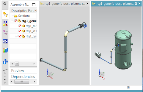
Tabbed windows allow you to quickly navigate between open routing assembly models. All commands available for a routing part retain their functionality when you switch to the window containing the part. Also, routing presets, navigator settings, license options, command histories, Undo histories, etc. are retained for each part.
Improved loading of routing objects
For better usability of routing assemblies, NX automatically loads required routing data such as survey components and connections from the directly subordinate elements of the routing assembly when the following applies:
- A routing assembly is defined as the active part.
- A routing application is set as the current application.
To use these extensions, the part must be opened and saved in NX 12.
3.5.8 Cable duct properties - extensions
Routing, the following extensions have been added for better support of cable ducts.
Include oversize in calculation for filling
The new user standard Include Overstock in Fill Calculation allows you to include any oversize in calculations for filling cable chambers. If wire or cable bundles are covered with oversize, a cable duct may be overfilled due to the additional thickness of the oversize. Use this user standard when you need to check the effect of oversize in calculations for filling cable ducts.
UFD_Routing_Sort_Connections
The new sample plug-in UFD_Routing_Sort_Connections (UFD_Routing_Sort_Connections) shows how wire or cable connections are sorted based on diameter attributes (from the largest diameter to the smallest). You can enable the plug-in and change it to indicate which set of connections is first to be routed through a cable duct.
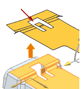
3.6. sheet metal
3.6.1 Disk - extensions
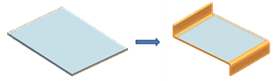
Creating a base plate
You can now:
Create a slab with multiple sections by selecting multiple inner closed profiles.
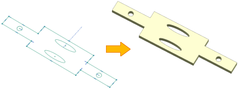
Use assembly references to create a plate with multiple bends, such as an interlocking bracket in an assembly. To do this, use the new Multi-Bend References options.
You can use the new Tab Curves presets to set presets for the bend center and tangential lines.
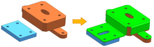
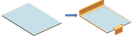
Creating a Secondary Plate
You can now:
Create a slab with multiple sections by selecting multiple inner closed profiles. You can also add material to a panel at multiple locations by selecting multiple outer closed profiles.
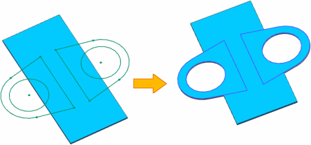
You can add material to a specified sheet metal body if a part file contains multiple bodies. To do this, use the new Select Body option.
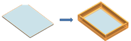
When is this function used?
You can use the extensions to create complex sheet metal parts, such as an interlocking bracket in an assembly with multiple cutouts and bends.
Where can this function be called?
| Application: | Sheet metal |
| Command search: | Plate |
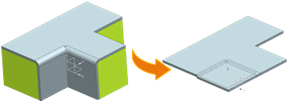
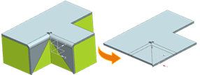
3.6.2 Processing - Enhancements
You now have the following options:
Control the orientation of the unfolding view for the upward face with nonlinear edges. Specify a KSYS when defining the orientation.
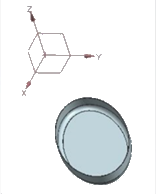 |  |  |
| Part without linear edge | Unfolding view with orientation method of type Standard | Oriented unfolding view; after specified KSYS has been dragged to reference KSYS |
Display holes smaller than or equal to a specified diameter value as center markers in the unwind view. This is useful when holes require a different manufacturing process.
Create an associative unfold and a solid with fixation to the current timestamp. You can also create a unwind and a face body as non-associative to the parent body.
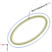
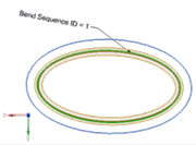
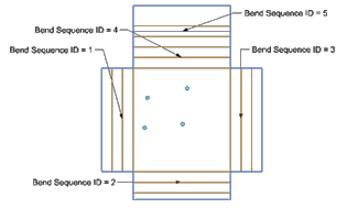
Use the Bend List command to edit the bend properties, such as bend sequence and bend name, after the unwind view is set as the active view.
In the Sheet Metal Preferences dialog box on the Flat Pattern Treatments tab, the name Corner Treatment Options has been renamed Treatment Options. In addition, hole treatment options have been added to define and treat the small holes in the part in the unwind views.
Where can this function be called?
| Application: | Sheet metal |
| Command search: | →Upgrade →Surface body →Bending list |
3.6.3 Functional extensions of the "Flange" command
You now have the following options:
Create multiple flange copies by selecting multiple base edges within a single flange form element.
Add more than one set of edges and define parameters such as length, angle and bending radius for each set.
 |  |  |
| Flange with two sets, each with only one base edge and unique direction | Flange with two sets, each with only one base edge and clear width | Flange with only one set |
Avoid penetrations when creating flanges on adjacent edges in a given set. To achieve this, you can apply a miter. To do this, activate the Miter check box in the Flange dialog box.
 |  |
| The adjacent flange copies are not in the same set: Mitre is not applied. | Adjacent flange copies are in the same set: Mitre is applied. |
Apply unique corner and bend clearances to each set of flanges.
Create the flange form element successfully even if some of the flange copies in a set fail.
Apply bend clearances to the flanges when the Flange Inset is set to Bend Outside.
 |  |
| Square bend release | Round bend release |
Activate mirror and pattern commands to replicate geometry independently of form element parameters. To do this, use the new Enable Geometry Mirror and Pattern check box.
Where can this function be called?
| Application: | Sheet metal |
| Command search: | Flange |
3.6.4 Extension of the option "Convert to sheet metal"
You now have the following options:
- Remove corners of an imported or non-plate geometry while converting the geometry to plate.
- Convert a local area, such as a single face or a group of joined faces, to sheet metal.
When will this function be used?
The extensions allow you to successfully add sheet metal form elements such as Flange, Connect Corner, Undo Bend, and Unfold.
Where can this function be called?
| Application: | Sheet metal |
| Command search: | Sheet - Convert to Sheet Metal |
3.6.5 File for material standards and bending table - extension
When you run the Sheet Metal application, the software now displays a warning message indicating a change in the material standards file.
The Material Standards file and individual tables such as Material, Bend or Tool table are now versioned. This allows file format changes to be tracked in future NX versions.
You can now:
Create a separate file for material standards for English and metric units. Use the metric part and English unit user standards to specify the file path.
Use the Internal (INSIDE) and External (OUTSIDE) methods to control the bending angles defined in the bending and tool tables.
Calculate the neutral factor value using one of the following bend definition methods:
- Bending Formula (Bend Allowance Formula)
- Bend Deduction Formula
- Bending formula DIN6935 (DIN6935 Formula)
- Tables Bend Allowance and Bend Deduction
Control the bending angle and K factor in the material table by defining the global tool set combination of the punch (P) and die (D).
In the material table, select both the material and the tool. This is possible because the tool table is located in the material table.
Define multiple secondary tables in the Material Standards file, using the bending angle and thickness to calculate the bending radius and K-factor.
Add more columns to the material table to create additional part attributes. You can define a title and value for each attribute.
Define the Relief Depth and Relief Width in the Material table.
3.6.6 Replace form element
You can use the Renew Feature command to recalculate form elements created in earlier versions of NX in the current version of the form element. When you regenerate a form element, you create it so that it is faster and more accurate than the original version of the form element.
Unlike form element rendering, which recreates a form element in its original form element version, the Renew Feature command recreates a form element using the current version of NX.
In the Renew Feature dialog box, the software displays the list of renewable form elements, including form elements that are hidden, suppressed, or inactive.
Where can this function be called?
| Application: | Sheet metal |
| Command search: | Renew form element |
3.6.7 Tear open edges - extension
If you create a crack in a sheet metal part, you can now:
| Use any of the following curve types | |
| Linear |  |
| Non linear | 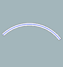 |
| Tangential | 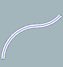 |
| Not tangential | 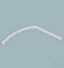 |
| Cutting | 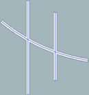 |
| Define the width and shape of the end surface | |
| 1. tear-off width 2. end cap shape | 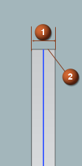 |
| Round sharp corners by using fillets |
 |
To support these extensions, there is the new Edge Rip node under Sheet Metal in the Customer Defaults dialog box.
When will this function be used?
The extensions allow you to define sections with different shapes and widths in sheet metal parts.
Where can you call this function?
| Application: | Sheet metal |
| Command search: | Break edge |
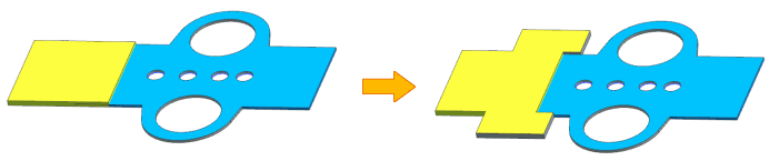
3.6.8 Paragraph - Extensions
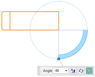
You can now create a paragraph at any angle between 0 and 180° with a single profile that is linear or oblique.
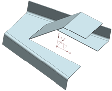 | 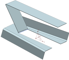 |
| 45° | 135° |
When is this function used?
The extension allows you to create an angled paragraph on a planar surface. You can use such paragraphs to give a part more clearance or rigidity.
Where can this function be called?
| Application: | Sheet metal |
| Command search: | A paragraph |
3.6.9 Sheet metal from solid bodies - extensions
When you create a sheet metal body from a solid, you now have the following options:
You can specify bend parameters, such as bend radius, K-factor, and bend clearance, for each bend edge. You can also edit each bend parameter individually.
You can hide the parent body to display the resulting sheet metal body.
 |  |  |
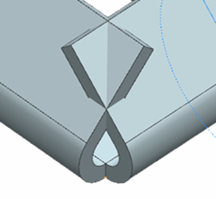
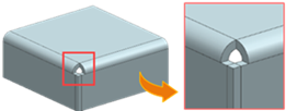
When you create a sheet metal body from a body, NX now proceeds as follows:
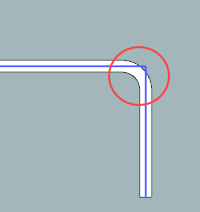
It creates a clean open corner at the point where two or three bends meet
 |  |
| Before | After |
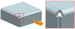
It prevents penetration of overlapping and intersecting adjacent bending surfaces in the formed and unwound state. The output geometry is consistent regardless of the order in which you select the faces.
 |  |
| Before NX 12.0.2 | NX 12.0.2 |
 |  |
When is this function used?
The extensions allow you to create a valid sheet metal body from the solid body with cleaned open corners. You can then directly perform sheet metal operations on the resulting body and create complex sheet metal parts.
Where can this function be called?
| Application: | Sheet metal |
| Command search: Sheet metal off body |
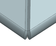
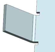
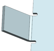
3.6.10 Bridge connections - extensions
You can now connect sheet bodies using the linear edges of concatenated extended flanges and concatenated contour flanges.
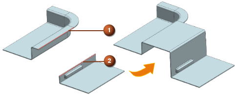
1. starting edge 2. end edge
You can now create a bridge fillet form element of type Fold transition between the linear edges of the planar bend faces of the following two sheet bodies:
- A body containing a concatenated extended flange or concatenated contour flange,
- A body that contains neither a complex shape element, such as a concatenated extended flange or concatenated contour flange, nor a relief cutout or setoff.
Where can this function be called?
| Application: | Sheet metal |
| Command search: | Bridge fillet |
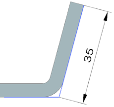
3.6.11 Flange extensions
If you create a flange, you now have the following options:
You can define the length of the unwound flange from a tangent to the outer bend. This corresponds to DIN standard 6935.
Note that the measurement of the length of the flange from the tangent depends on the angle of the outer bend.
 | 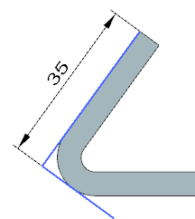 |
| The angle of the outer bend is less than 90° | The angle of the outer bend is greater than or equal to 90° |
| If the angle of the outer bend is less than 90°, the tangential length is measured with the intersection of the outer surfaces. | If the angle of the outer bend is greater than or equal to 90°, the tangential length is measured from a plane that is tangential to the outer bend surface and perpendicular to the dimension. |
You can specify that the flange body is on the inside of the bend and you can specify that the material originates from the edge opposite the selected reference edge. To do this, use the new OML (Material Inside OML) option.
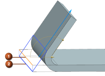
1. selected reference edge 2. material inside opposite the selected reference edge
To align these extensions with the flange form element, the DIN 6935 (DIN6935) option has now been renamed to Tangent in the Advanced Flange dialog box.
When is this function used?
The extensions allow you to define the flange length in a way that would be measured directly on the finished product. This method is useful when you measure the dimensions of sheet metal parts and check them if they are greater than or equal to 90°.
Where can this function be called?
| Application: | Sheet metal |
| Command search: | Flange |
3.6.12 Check-Mate check function for sheet metal cutouts
Use these new inspection functions to inspect the shape and size of cut-out form elements on a sheet metal product:
| Check cut-out shape: | Checks whether the cut-out shape elements have a standard shape for cut-out shape elements, such as round, slot, square, rectangle, and hexagon. | |
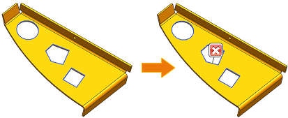 |
||
| Check portal size: | Checks whether the size of the portal form elements matches the specified portal size limit. |
When is this function used?
You can avoid unnecessary production costs resulting from problems with cut-out shape and size.
Solid Edge
1. Solid Edge 2023 Update
Teamcenter Documentation
1. Overview
2. Teamcenter Basics
3. Working in Teamcenter
4. Working with CAD applications
5. Working with the structure manager
6. Workflows in Teamcenter
EPLAN - integrate2
1. Preamble
2. Function Description
3. Operating the Integration
4. Troubleshooting