User Tools
This is an old revision of the document!
Table of Contents
3. Design
3.1. sketch preparation
3.1.1 Sketch section view
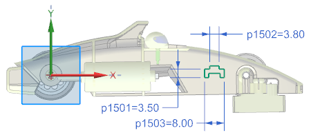
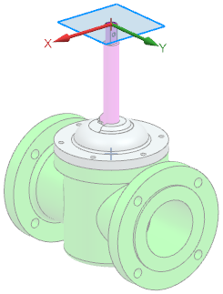
In the Sketch Task Environment application, you can view a sectional view of a part to better visualize its inner details and dimensions as you sketch. The sketch plane is automatically used as the section plane. You can also display a slice of your section view or automatically reverse the section view when you rotate your model.
Display a sectional view
 Cut Cut |
| To see the inside of your part on the sketch plane, use the Section command to display a section view of your part. In this example, the Sketch Emphasis command is used to highlight the active sketch. |
Splitting the section view into layers
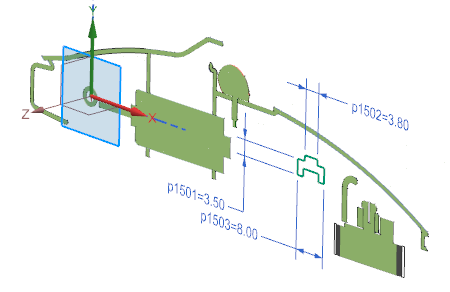
 Slice Slice |
| To display a layer of your part when sketching, use the Layer (Slice) option. |
Reverse a sectional view
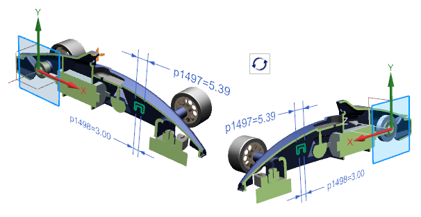
 Reverse cutting direction automatically Reverse cutting direction automatically |
| If you want to reverse the sketch intersection direction automatically when you rotate your model, use the Auto Reverse Section Direction option. |
Where can this function be called?
| application | sketch task environment |
| Menu ribbon | Register Home page (Home) → → Group Sketch → Section (Section) Home Tab → → Sketch Section Group → Layer (Slice)  } }Home Tab → Sketch Section → Auto Reverse Section Direction  |
3.1.2 Creating alignment constraint conditions
Use the Create Alignment Constraints user standard to control whether Horizontal Alignment  and Vertical Alignment
  are automatically determined when you create curves.
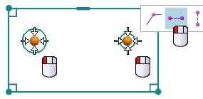
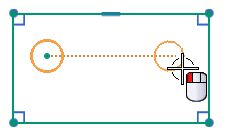
In this example, a second circle is placed to the right of the left circle. Note that the center of the second circle snaps so that it is aligned horizontally with the first circle. However, a horizontal constraint is only determined automatically if the user standard Create Alignment Constraints is set.
 |  |
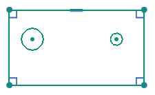 | 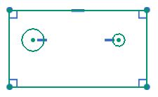 |
 Create alignment constraint conditions Create alignment constraint conditions |  Create alignment constraint conditions Create alignment constraint conditions |
If Create Alignment Constraints is enabled, you can manually disable alignment constraints in the Inferred Dimensions and Constraints dialog box. If the user default is disabled, the Horizontal Alignment and Vertical Alignment options are not displayed in the dialog box.
When is this function used?
You can control whether horizontal and vertical alignment constraints are automatically determined when you create curves. By default, the Create Alignment Constraints user standard is disabled and no alignment constraints are automatically determined during curve generation. In NX 11, the horizontal and vertical alignment constraints are automatically determined by default.
Where can this function be called?
| Application | Sketch |
| Prerequisites | The user standard Create Alignment Constraints must be activated. |
| Command Search | Determined Constraints and Dimensions |
| Position in dialog window | Horizontal alignment Vertical alignment |
3.1.3 Sketch highlighting
Use the Sketch Emphasis command to quickly identify the active part when you create a sketch in the assembly context in the Sketch Task Environment. This command enhances and replaces the Highlight Work Plane Emphasis command in the Sketch Task Environment, which, while paler in color for all objects that are not on the sketch plane, does not identify the active part.
 |  |
| Sket highlighting activated | Working level highlighting is activated |
When is this function used?
You can use this command to quickly see in which part you are creating a sketch. This allows you to avoid creating unintentional WAVE shortcuts and reliably select the correct active part before creating a sketch.
Where can this function be called?
| Requirement: | You must be in the Sketch Task Environment. |
| Command search: | Sketch highlighting |
| menu bar: | tab “home” → group “sketch → sketch highlighting |
3.1.4 Using multiple windows when creating sketches
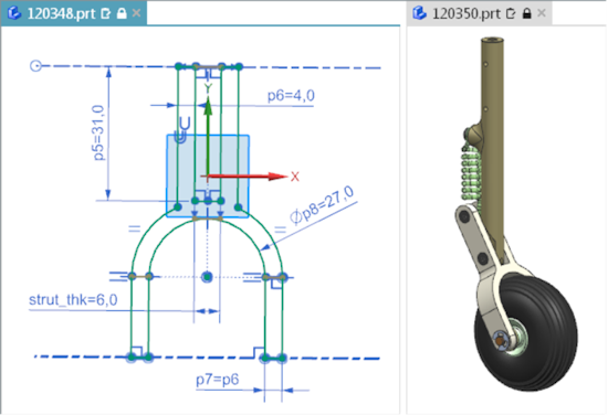
If you are working in the Sketch Task Environment and in Direct Sketch, you can now display multiple parts simultaneously in separate tab windows.
If the component you are editing appears in both windows, your changes are automatically applied to both windows.
In this example, a part on the left side and its parent assembly on the right side are open. You can view the updates to the part on the right as you create or edit the sketch.
If you create a sketch in multiple tab windows, you can do the following:
- Create components from the assembly in a separate window. With this method, you can only display the new component without manually hiding the other components.
- Reference a component to quickly create a similar sketch in a separate window because both components are displayed simultaneously.
- Change components in a single window. The changes are automatically reflected in all windows that display this component.
| Note: If you create the sketch directly in Construction, you have the following options: → You can hold and drag the mouse wheel or use the Spaceball to switch to another tab window. → You can quickly disable the sketch by clicking in another tab window. |
Where can this function be called?
| Application: | Construction |
| Prerequisite: | You must have several parts open. |
| Menu ribbon: | File tab → Window → Window layout → Select a command based on the desired arrangement and the number of parts to be displayed simultaneously |
3.2. construction
3.2.1 New construction commands
3.2.1.1 KSYS print
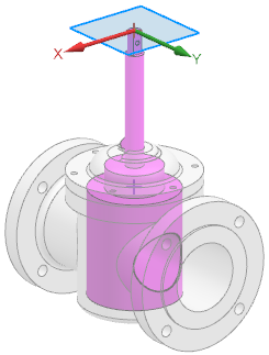
When designing a model, you can use the new Print CSYS command to create a coordinate system that defines the print direction that will be used later in 3D printing.
You can manually define the orientation of the Print KSYS command or you can leave it to NX to suggest an orientation that will cause significant smoothing of the part when it is printed. The result is a new KSYS shape element that is positioned so that the part rests on the XY plane and the creation direction is aligned in the +Z direction.
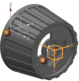 |
| (1) Absolute reference KSYS used in model building (2) KSYS for printing is aligned to smooth the part for printing |
You can now use the following commands to add a print coordinate system to a model:
- Check clamped supports
- Check maximum overlap angle
- Check printable volume
In these cases, NX adds a new KSYS to the model for printing and determines its placement using the currently specified design plane KSYS.
Where can this function be called?
| Application: | Construction, manufacturing |
| Command Search: | KSYS print |
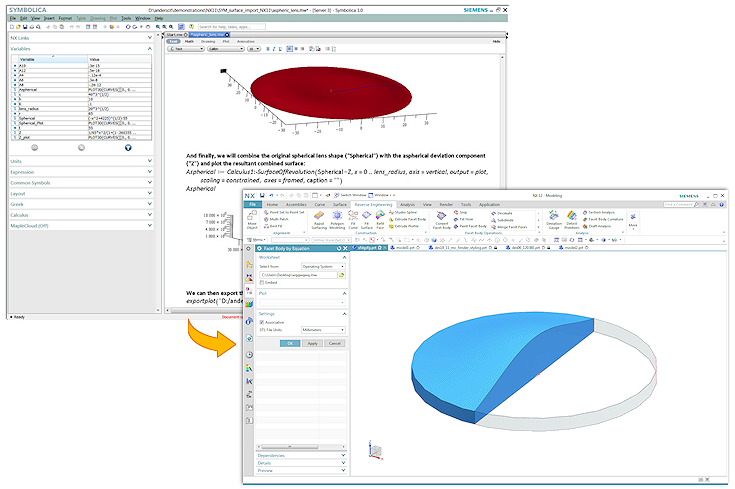
3.2.1.2 Body by equation
Use the Body by Equation command to import complex, mathematically defined surfaces into NX as convergent facet bodies from Symbollica.
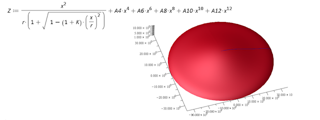
The new NX form element is connected to the corresponding Symbolica output worksheet and the STL output file of the 3D plot. Each time the Symbolica worksheet is changed, the linked NX facet body is updated.
You can import Symbolica output worksheets from the following locations:
- A directory in the operating system.
- A Teamcenter position
- A Symbollica worksheet previously embedded in the NX part file.
When is this function used?
Use the Body by Equation command when you need equation-controlled bodies and surfaces in applications that integrate the laws of physics into their constructions. Examples include the space and automotive industries, shipbuilding, and optical industries.
- By creating equation-controlled bodies, there is no need to use techniques that can lead to errors, e.g. cutting and longitudinal direction or other non-associative, approximate development techniques.
- You can use the Body by Equation command in conjunction with Converging Construction to use equation-controlled bodies directly in NX Construction. This results in improved accuracy and reduced design time.
Where can this function be called?
| Application: | Construction |
| Prerequisite: | You must have access to Symbollica or Maple (.mw) worksheet files. |
| Command search: | Body by Equation, Symbolica |
3.2.2 Command, tool and selection - extensions
3.2.2.1 Defining print marks
When constructing a model, you can now use the Text command to define areas as print marks that determine where text markers, such as serial numbers or date codes, should be applied in the later 3D printing process.
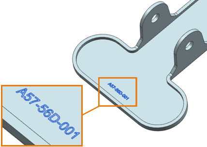
The resulting Print Mark text form element can be aligned and has an attribute that identifies it as special dynamic text. You can use asterisks (*) as placeholders for variable text, which is replaced by single characters or digits in the string during additive manufacturing.
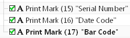
Print marks in Parts Navigator
- The generated form element displays the same or other text form elements in the Part Navigator, but is not labeled with text, but with print mark.
- To distinguish between print marks, you can assign a unique usage label to each of them.
Where can this function be called?
| Application: | Construction, manufacturing |
| Prerequisite: | Define the user standard Show Additive Manufacturing-specific Dialog Items in Modeling Commands. |
| Command search: | Text |
| Position in the dialog window: | Group Print Mark Settings |
Solid Edge
1. Solid Edge 2023 Update
Teamcenter Documentation
1. Overview
2. Teamcenter Basics
3. Working in Teamcenter
4. Working with CAD applications
5. Working with the structure manager
6. Workflows in Teamcenter
EPLAN - integrate2
1. Preamble
2. Function Description
3. Operating the Integration
4. Troubleshooting