User Tools
Table of Contents
2. Functions
2.1. AutoCAD 2020
2.1.1 Blocks pallet
Several methods for inserting blocks are currently available: Insert, Tool Palettes, and DesignCenter. Having these different options available recognizes that people in different disciplines have different requirements and preferences.
The main reason for redesigning the Insert dialog box is to better visualize blocks in the Insert Block workflow. The palette increases efficiency when searching and inserting multiple blocks - including the new Repeat Placement option, which can save you a step.
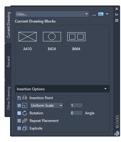
The main features of the new Block Palette make it easy to efficiently specify and insert blocks from a recently used list or from specific drawings. Three tabs provide access to the following information:
- The Current Drawing tab displays all block definitions in the current drawing either as symbols or as a list.
- The Recently Inserted Blocks tab displays all recently inserted blocks regardless of the current drawing. These remain between drawings and sessions. You can remove a block from this tab by right-clicking it and choosing Remove from Last List.
- The Other Drawing tab provides a way to navigate to folders from which you can select drawings, either to insert as blocks or to select from the blocks defined in these drawings. These drawings and blocks also persist between drawings and sessions.
The upper part of the palette contains several controls, including a field for applying wildcards to block names and several options for different thumbnail sizes and list styles.
2.1.1.1 Access to color ribbons
Top Page tab > Block button > Insert.
Ribbon access provides a gallery of blocks available in the current drawing along with two new options, Recent Blocks and Blocks from other Drawings.
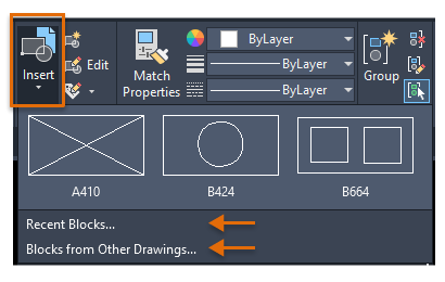
These two options open the Blocks palette either on the Recent tab or on the Other Drawing tab. The Current Drawing tab in the Block palette displays the same blocks in the current drawing as the string gallery. Blocks from the Block Palette can be placed by dragging and dropping or clicking and placing.
2.1.2 New conception of the clean-up function
The cleanup function has been revised to facilitate the cleanup and organization of the drawing. The control options are almost identical, but the alignment is more efficient and the preview area is now resizable.

- Note that you can now clean a zero length geometry without cleaning empty text objects.
- The check boxes in the Named Unused Items pane allow you to select cleanable items by category and individual items.
- The Find Non-Purgeable Items button displays information about why the item being checked cannot be cleaned, which is helpful in many cases.
- For items that cannot be cleaned, the new design provides advanced information as shown below, including the number of items at each level and their impact on file size. The Select Objects button, shown in the figure below, magnifies the specified objects that cannot be cleaned.

2.1.2.1 Access to color ribbons
Management tab > Cleanup window > Find and rinse non-rinseable items.

2.1.4 Improvements in DWG comparison
The primary extension of the DWG Compare function is that you can now compare and edit the current drawing directly with a particular drawing in comparison mode. The comparison takes place in the current drawing. Any changes you make to either the current drawing or the compared drawing are dynamically compared and highlighted.
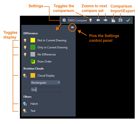
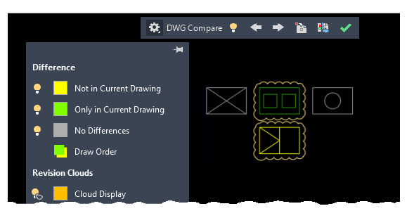
To facilitate direct editing in the comparison state, the options and controls for this function have been moved from the ribbon to a docked toolbar at the top of the drawing area. Most options have been combined in the Settings control and expanded as shown. You can easily toggle the comparison via the toolbar and display the types of differences via the Settings Controller.
You can also easily change the default colors by clicking a color for your settings or for color-blind colors. In this illustration, the color for Not in Current Drawing has changed from red to yellow.
For example, suppose you need to compare the differences between two highly complex drawings that have been simplified to look like this:
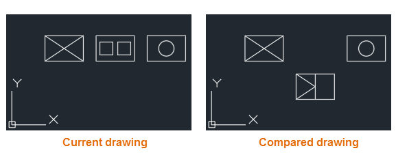
The result of comparing the current drawing with the compared drawing is as follows:
The change sets are each surrounded by orange revision clouds that are scaled to the drawing dimensions.
- You can import the differences marked in yellow from the comparison drawing into the current drawing. If you do this, these objects now exist in both drawings and automatically turn gray. Only the objects in the specified area that are not contained in the current drawing can be imported.
- You can also export both drawings to a new snapshot drawing that combines the similarities and changes between the two drawings.
- The result of this operation is the same as a drawing comparison in AutoCAD 2019.
- The arrow keys provide a way to navigate through each change set and automatically zoom to any subsequent or previous change set.
2.1.5 Measure geometry option: Fast measurement
Measuring has become much faster with the new Quick option of the MEASUREGEOM command. With this option you can quickly check the dimensions, distances and angles within a 2D drawing.
When this option is active, the command dynamically displays dimensions, distances and angles within a 2D drawing when you move the mouse over and between objects. The orange squares on the left side of the figure represent angles in exactly 90 degrees.
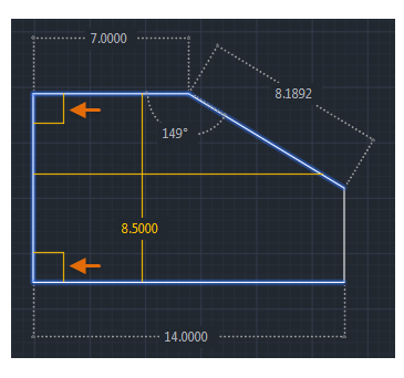
The distance between the two objects is measured in the following figure because they are parallel.

To avoid fast dimensional disruption and improve performance, it is best to zoom into complicated areas.

2.2 AutoCAD 2018
2.2.1 Improvement of the XREF layer properties
To provide more flexibility in controlling XRef overrides, new controls for managing XRef layer properties have been added to the Layer Settings dialog box, which can be accessed from the Layer Properties Manager. If the option to keep XRef layer overrides with the VISRETAIN system variable is enabled, you can now specify which XRef layer properties you want to reload. The individual layer property options are stored in the registry as specified by the new VISRETAINMODE system variable. The Layer Properties Manager also includes a new status icon to indicate when a layer associated with an XRef contains overrides.
Primary Commands and System Variables: LAYER, VISRETAIN, VISRETAINMODE, XREFOVERRIDE
2.3 AutoCAD 2017
2.3.1 Assocative center points and center line
You can create center points associated with arcs and circles, and center lines associated with selected line and polyline segments. For compatibility reasons, this new feature does not replace the current methods, but is provided as an alternative.
Primary Commands: CENTER MARKING, CENTER LINE
2.3.2 Coordination Model: Object Snap Support
The default object snap for 2D endpoints and midpoints allows you to specify exact positions in an attached coordination model.
Primary System Variable: CMOSNAP
2.3.3 Improvements to Layergroup Manager and Mechanical Layer Manager
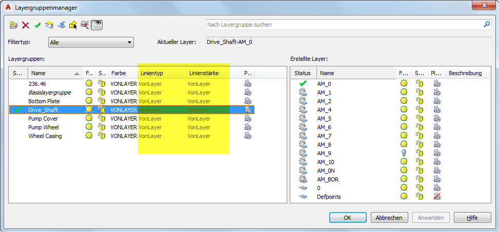
In the Layer Group Manager, you can now specify the line type and thickness of the layer group, just as you specify the layer group color.
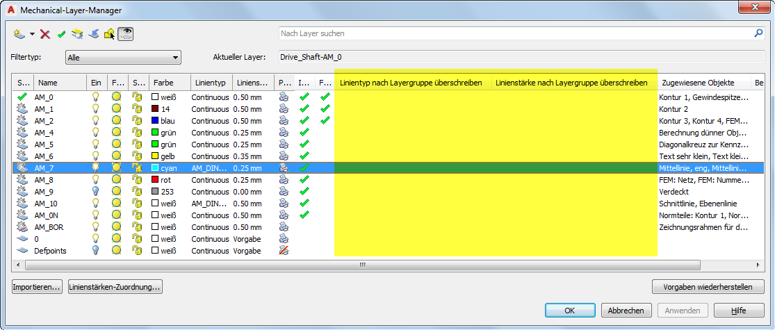
In the Mechanical Layer Manager you can select whether the line type and the line thickness of the layer should be overwritten with the corresponding values of the layer group.
2.3.4 Improvement of leadership line comments
The AMNOTE command has been improved to display a context-sensitive ribbon instead of the Annotation icon dialog box.

The context-sensitive ribbon tab is displayed when you select points for the vertices of the leader line. A direct edit editor allows you to enter the annotation text in the same way as the MTEXT command. All the functions that were available in the Annotation Icon dialog box are also available in the new context-sensitive tab. If you prefer to continue using the Annotation Icon dialog box, you can disable the context-sensitive tab by setting the AMNOTETAB system variable to 0.
2.3.5 Enhancements to the tools for creating rectangles
The commands for creating rectangles that were previously accessed from the Rectangles dialog box are now available directly from the ribbon.
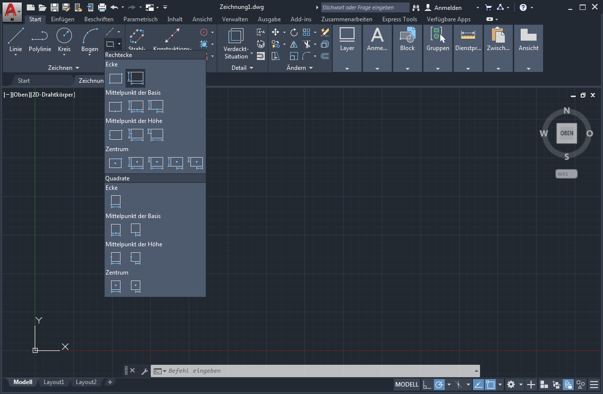
With these commands, you can now preview the rectangles, making it easier to place them in the drawing area. The commands have also been improved to support dimension input, making it easier to specify the exact base and height.
Solid Edge
1. Solid Edge 2023 Update
Teamcenter Documentation
1. Overview
2. Teamcenter Basics
3. Working in Teamcenter
4. Working with CAD applications
5. Working with the structure manager
6. Workflows in Teamcenter
EPLAN - integrate2
1. Preamble
2. Function Description
3. Operating the Integration
4. Troubleshooting